
Free Flight INDOOR
Bud Tenny
MAKE READY! This is the time of the year that indoor fliers begin to think about the upcoming contest season. Don't do like I do—put off looking at the models until the night before the contest. I usually find out that there are warps in the paper-covered models, holes in the microfilm models, and the only rubber I have stripped is for the model that was destroyed last spring while trying to balloon it down from the rafters! Besides all that, I used the last of the patching film last spring, and there isn't a single sheet of film in storage. Wise up!
Check the tool kit! If your models are ready, how about the tool kit? Have you replenished the pins, cleaned out the dried-up glue gun, bought some new CyA (cyanoacrylate) glue, replaced the X-Acto blade, repaired the run-down stand, replaced the dirty wiping rags, etc.?
- Replenish pins
- Clean out dried-up glue gun
- Buy new CyA glue
- Replace X-Acto blade
- Repair or replace run-down stand
- Replace dirty wiping rags
How many of the tools normally carried in your indoor tool kit are still in your outdoor FF box? Are your made-up motors in proper order? Did you clean them up last spring and store them in a cool place? How about making sure your flight log has enough fresh pages? Time's a-wastin'!
Sad news. One of the bright lights of the Eastern Seaboard, Ed Whitten's New York Indoor Times newsletter, was a bit darker this issue. It seems that not only were they not able to arrange for the Nassau County Arena in Long Beach to remain open, but it seems almost certain that the Low Library Rotunda of Columbia University will not be available this year. Ron Williams is no longer on the staff at the university, and no one has stepped forward to sponsor the activity. So, let's wish the New York bunch well in their search for a place to fly. It is time also for all those fliers to acknowledge their indebtedness to Ed Whitten and Ron Williams for all the hard work and leadership over the past several years.
Rubber testing. A while back, I remarked on the coming shortage of good rubber once the Pirelli source dried up. I also noted that we need a definitive test of rubber quality, one which is nondestructive, yet tests the rubber to almost-breaking stress. That is, a test that will serve competitors well. So far I've not heard a test described which meets these goals.
FF Indoor/Tenny
If you have argued the subject to death and are content with equal-leg gussets, then what Nat says is absolutely true. Since that description must cover at least 90% of free flight models, we apologize for not reminding you about the humble razor saw and an off-the-shelf miter box.
For smaller gussets—and especially with soft balsa—the use of a single-edge razor blade is more appropriate than a razor saw, and that is where some of the home-brew miter boxes—which is what they are—come into play. Also, one scheme we showed was for cutting unequal-leg gussets of any desired proportions. On Nordic Glider trailing edges, for example, where the undercambered ribs tend to be a mite weak, unequal-leg gussets have a slight advantage; the long leg is glued to the side of the rib.
Bob Meuser, 4200 Gregory St., Oakland, CA 94619
Testing methods
One of the best-documented tests for model rubber was developed by Fred Pearce. His test consisted of stretching a loop of rubber to about eight times normal length, holding the extension for three minutes, then recording the extension. The loop was then relaxed a few inches at a time while the tension was measured at each relaxation interval (5 in., for example). The length of the rubber was then carefully measured and its weight recorded. The pounds of force (tension) were recorded at each relaxation interval, and the force readings summed.
Fred is a Wakefield flier, so Dennis Jaecks decided to refine the method for indoor. Dennis describes the testing this way:
- Stretch the test loop of rubber until the tension equals force F1. F1 is computed by this formula:
F1 = (45 × rubber weight in grams) / (loop length in inches)
- Record loop length L1 at force F1.
- Stretch the loop again to force F2, where:
F2 = (430 × rubber wt. in gm) / L1
- Record loop length L2 at force F2.
- Relax the loop by 3 in. and record force F3.
- Continue to relax the stretch by 3 in. and record each force.
- Calculate the energy stored by summing the following series:
(F2 − F3)/2 + (F3 − F4)/2 + ... + (Fn−1 − Fn)/2
Finally, compute energy storage E in ft.-lb./lb. using: E = .25 ft. × 16 × (force summation)
FF Indoor/Tenny
Continued from page 155
How do I use the result? There are two ways to use the data generated by this test. First, Fred's analysis included dividing L2 by L1; if the result was 7.3 or less, the rubber was too hard (old) for effective use; if this value of elongation was greater than 8.2, the rubber was too soft for effective use. In the case of high-elongation values, the rubber may test better later if it is stored carefully (cool and dark, with no chemical fumes).
At one time, I did some tests which included alternate heating and cooling cycles under carefully controlled conditions. I was not able to reach a meaningful conclusion due to inadequacies in the before/after evaluations, but I still believe that some rubber under some circumstances can be improved by artificial aging.
The second use for the data generated by this test is to directly compare the energy storage data for different batches of rubber. For a similar elongation value, the rubber able to store higher amounts of energy will be the best. I also believe that different propeller/model combinations work better with different elongation values, but I have no hard data to support this idea. It would require a very large amount of testing to prove or disprove that concept.
Got a torquemeter? Anyone who is reasonably serious about indoor flying should have a torquemeter. No matter what the ceiling height, if your model can outfly the ceiling you need a torquemeter; the lower the ceiling, the more you need it. Let's see why.
First, the amount of torque in the motor at launch determines very closely how high the model will climb. If you have data on how high a particular model/prop/rubber combination climbed, you can learn to get the model within inches of the ceiling repeatably. This is particularly important if the ceiling is full of things to hang up on.
Second, if you are flying to win, you must wind the motor almost to breaking each time. If that's too much launch torque, slowly unwind to the correct torque, hook up, and launch.
Why back off turns? I'll cover this in more detail another time, but basically, winding all the way and then backing down leaves up to 25% more turns in the motor than if you simply wound up to the launch torque. Not only that, you have a very repeatable technique which allows you to keep good records that are useful at future contests. Finally, if the winding is done correctly, the model's cruise and letdown will go better.
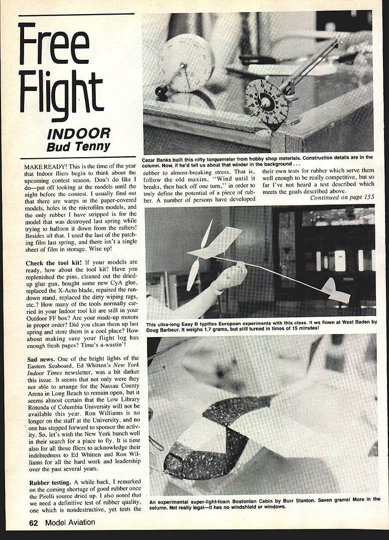
Roll your own! One photo shows the excellent torquemeter developed by Cezar Banks; it can be built entirely from materials from the local hobby shop. As shown, the torquemeter mounts on a swivelled yoke which clips into a clip mounted on Cezar's model box. If you can get the general idea from the photo, the following description may get you started (otherwise, I'll send a photocopy of Cezar's sketch if you send me a SASE with your request).
The main body of the torquemeter is 3/32-in. brass tubing, with Peck model PA-6 nylon thrust bearings in each end. The torque element is .015 music wire, wrapped and soldered to 3/32-in. tubing. The 3/32-in. tubing is long enough to form into a hook after it passes through the front thrust bearing; grind the tip of the hook into a smooth taper to allow easy removal of the rubber. In the back, the 1/16 music wire passes through the rear bearing and is secured with a Goldberg WC116 wheel collar. Use a long 2-56 screw to mount the wheel collar, so the screw can serve as a rotation stop. Another wheel collar is secured to the front hook using a 2-56 Nyrod adapter about an inch long inserted over the set screw; this serves as the pointer.
You may not be able to see it clearly in the photo, but the dial has an extension which sticks out 1/2 in. below the 2-in. diameter dial. This extension is drilled to allow the release lever to pass through. The release lever extends back along the length of the brass tube past the screw-stop in the back when it is in the "unoperated" position. When you pull the release lever forward, the torque element is allowed to rotate to release turns. During launch preparation, this allows you to grab the motor close to the hook and then spin out a few turns. This will open a loop of rubber which is easy to hook up to the prop shaft. After the flight, you can spin off the rest of the turns to let the motor rest.
Once the unit is complete, you can calibrate it in arbitrary units (linear scale), or you can arrange a beam balance which applies torque to the rod. Initially balance the beam, then hang a 1-oz. weight exactly 1 in. from the beam center line. This will twist the wire until the beam is level; then mark the dial at the end of the pointer. Repeat this operation, moving the weight 1 in. at a time, until the torque range you need has been calibrated. Cezar transferred the calibration to colored vinyl sheet with rub-on decals, then protected the finished dial with clear mylar tape. It looks great!
Free Flight: Indoor
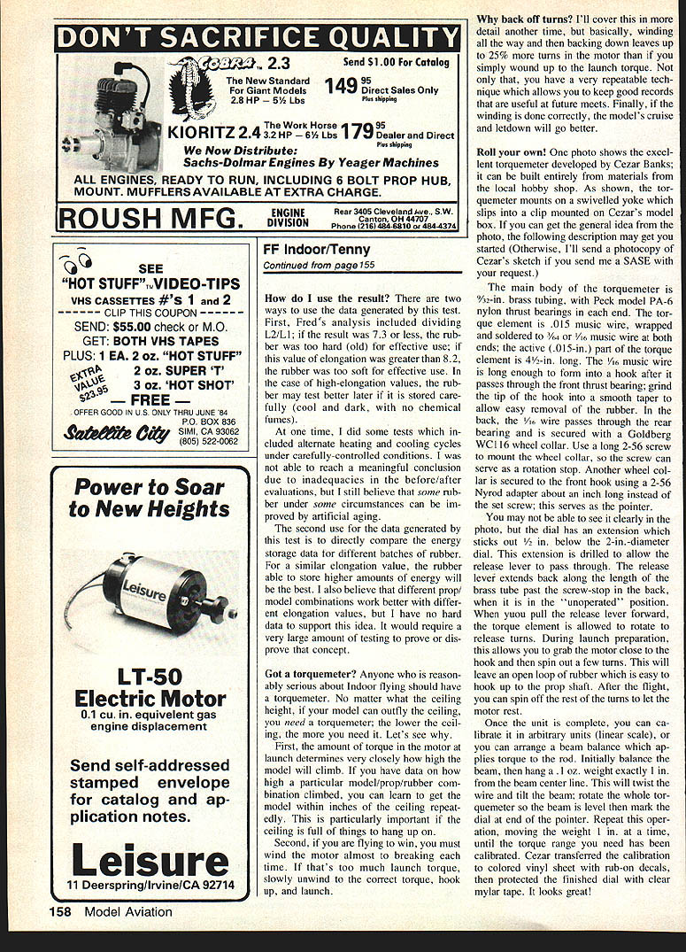
Another photo shows the latest trend in Easy B design—the "Swiss-type" layout. Actually, Otto Rodenburg of Holland flew a similar Easy B at West Baden after the 1980 World Championships, and the layout has seen extensive development in England. At least one proposal for an international class fitting this layout has been considered by the FAI, but nothing has been adopted so far.
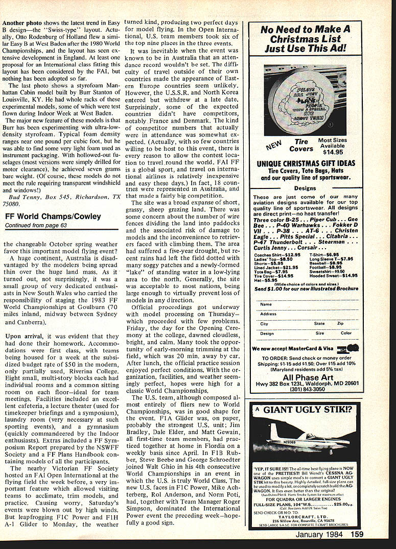
The last photo shows a styrofoam Manhattan cabin model built by Burr Stanton of Louisville, KY. He had whole racks of these experimental models, some of which were test-flown during Indoor Week at West Baden.
The major new feature of these models is that Burr has been experimenting with ultra-low-density styrofoam. Typical foam density ranges near one pound per cubic foot, but he was able to find some very light foam used as instrument packaging. With hollowed-out fuselages (most versions were simply drilled for motor clearance), he achieved seven grams bare weight. (Of course, these models do not meet the rule requiring transparent windshield and windows.)
Bud Tenny, Box 545, Richardson, TX 75080.
Transcribed from original scans by AI. Minor OCR errors may remain.

