
Free Flight: Indoor
Bud Tenny
OUCH! Twenty-twenty hindsight! After checking what I've said about prop wobble, I need to stress one point again. Indoor props don't wobble because of a weight imbalance—at least not for any reasonable amount of static imbalance. The problem is caused by structural or aerodynamic mismatch between the blades, and all reasonable care to match blades will pay off. This is because the amount of energy dissipated by the prop is much greater than the wobble force caused by a weight mismatch. A vivid example is the Easy B with one prop blade broken off. You can static-balance the remaining blade, but you won't do much for the wobble. Because of the loading on the single blade, the only way to demonstrate that the prop was balanced would be to run it in a vacuum!
Actually, the heavier the prop in relation to its size and the power driving it, the greater the effect a weight mismatch will be. For example, consider the amount of power dissipated by FAI Indoor props and Pennyplane props. Dennis Jaecks used 18-in. diameter, 27-in.-pitch props on his biplane Pennyplanes. FAI props go up to 22-in. diameter with pitch ranging to 40 in. Typically, the Pennyplane prop weighs three times as much as the FAI prop, handles twice the peak torque, and cruises at 2-1/2 times the rpm. With moderate care, the Pennyplane prop structure can be adequately matched between blades. The FAI prop is harder to match properly during construction, partly because it is a built-up structure whose stiffness is dependent on structural matching and on how tight and uniform the covering is. Even so, neither type prop will suffer from an equivalent lack of balance if the extra weight does not change the spar.
Prop-spar matching is obviously important to smooth running. Two types of spars are normally used—round and square:
- Round spar.
- Square spar: Years ago Bill Bigge calculated that a square balsa spar would be lighter than a round spar for equivalent stiffness (see Figure 1). Using the Chilton sanding guide described in my June 1986 column, the square spar is easier to make.
Once the spar is made and matched, the shaft must be attached. A few fliers mount the shaft on the diagonal (Figure 2) to gain maximum stiffness in the prop's rotational plane. Theoretically, this minimizes both forward bowing and blade sweepback under full-torque stress. However, if the shaft is not precisely aligned with the spar diagonal, some difference in stiffness between the blades will be generated automatically. Consequently, the shaft is usually mounted perpendicular to one face of the spar (Figure 3). Of course the shaft should be truly perpendicular side-to-side; centering is supremely critical. End-to-end centering of the prop shaft is quite critical, since deflection-testing is made at matched distances from the end of the spar. After adding the shaft, the deflection in both front and side directions should be checked again before adding blades to the spar.
Built-up prop blades should have ribs made in pairs, one for each rib station in each blade. Take care to match the ribs in both length and cross section. The ribs should be of the correct curvature to contact both the building block and spar (Figure 4). Note that the rib will touch the spar at a corner. Stan Chilton recommends that the spar corner be burnished slightly flat just where the rib touches. This gives a wider glue surface and allows a stronger joint.
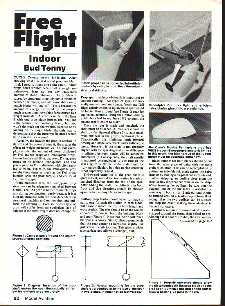
Jim Clem's Novice Pennyplane prop has WIDE blades! Since prop diameter is limited in this event, the high torque of the rubber motor must be absorbed somehow. Blade outlines for both blades should be cut from the same piece of balsa with the same grain orientation. This can be accomplished by putting an indelible ink mark across the balsa sheet and making a diagonal cut across its end. After stripping the outline piece from the sheet, a tiny diagonal cut remains on the strip forming outlines; be sure the diagonal cut/ink mark is oriented the same way on both strips. Blade outlines should be formed around a blade-shaped form thick enough that two outlines can be stacked atop one another, making identical size curvature. Typically, outline strips are soaked in water, wrapped around the form, then baked dry. Although it is a lot of trouble, the ideal outline form is twisted like a prop blade so that it will fit flat on the prop block. Thus, when the outline is formed, it is already properly curved and twisted. If this is not done, the outline should be fitted on the block during construction, moistened to relieve the stress of twisting, then glued to the ribs and spar after drying. Note that if the outline is moistened after being attached to the ribs and spar, the wood will expand and stress the whole structure.
Prop covering
Prop blades should be covered on the prop block, if possible. Otherwise, if water or saliva is used as adhesive, cover and trim the prop and return it to the prop block until all moisture has evaporated. Also, if the prop is not covered on the prop block, the film must be slack enough for the blade to lie on the film without distortion. If not, the blade twist may be changed during covering; the film will be too tight to let the blade assume the normal twist without stress.
Another important tactic is to be sure the film is attached to both the outline and the ribs. This accomplishes three things:
- If moisture is used as adhesive, the entire blade expands evenly, minimizing stress.
- The individual panels of film are small enough to stiffen the blade.
- Damage to the film in any single section won't spread to other sections.
Don't worry about wrinkles which appear as the blades dry out; a simple operation will remove them. Use a very fine artist's brush moistened with water to work out the wrinkles. Stroke the brush along each wrinkle; it will pull up level with the film around it. After all the wrinkles are treated, let the whole assembly dry again. Finally, store the prop in a holder which keeps the blades from touching anything.
Prop innovations
A number of different plastic props are available. One of the photos shows how to convert one to efficient pusher operation for Peanut Scale models. The free-wheeling feather on the front is trimmed flat to make a bearing surface. Then the shaft is projected through the hub and bent over to push against one blade. Al Backstrom flew this setup at Bedford Boy's Ranch in Bedford, TX.
Another photo shows the same basic prop hub as in Photo 1. In this case, the small plastic blades were removed and much larger balsa blades substituted. The model is a Profile Scale model flown by Randy Randolph, again at Bedford Boy's Ranch.
Novice Pennyplane has a rule limiting prop diameter, so how do you handle the power a three-gram model needs? Jim Clem is trying very wide blades: 2-1/2 in. wide on a blade which is only six inches long from shaft to tip. I'll report the performance as soon as I can get some numbers.
Next time: prop blocks and prop-covering techniques.
Bud Tenny, Box 545, Richardson, TX 75080.
Transcribed from original scans by AI. Minor OCR errors may remain.

