
Free Flight: Indoor
Bud Tenny
Steering problems
STEERING PROBLEMS. In the past 18 months or so, steering of AMA models has become an increasing problem — one which has three sources. The first source has been fliers who have increasingly expanded the scope of their activity, up to and including steering Lo-Cal Scale models.
The second part of the problem has been Contest Directors who let them do it, either for fear of being a "bad guy," or because they really don't understand the steering rules well enough. The third leg of the problem is those fliers who stood by and muttered under their breaths without filing protests.
I have four comments on this situation:
- It is the CD's obligation to be an SOB, if he needs to be!
- The steering rules are difficult to understand, even with the addition of a Contest Board interpretation. The whole matter probably will be reviewed in the next rules cycle.
- Steering works well at World Championships because the rules were written for that environment, and contestant meetings before official flying begins are used to be sure everyone understands exactly what is expected.
- Steering is an intentional part of the competition strategy in international competition. AMA Indoor fliers need to decide if this is a desirable philosophy for AMA competition before the rules can be fixed.
I have seven pages (single-spaced, in fine print) of comments which were circulated among Bud Tenny, Rick Doig, Del Ogren, and Bob B.
HLG altitude control
Many years ago, Hal Blubaugh of the Denver area reported interesting results using a "fence" or flap on the trailing edge of HLG wings. That is, a small strip of wood is glued vertically along the trailing edge, forming a vertical flap below the wing.
In my own experiments, I discovered that the glide path was less critical after warps were removed and washout used (as discussed in the July '87 column), but a different launch trajectory was often needed.
For small, peaked ceilings (or open girders), it is possible to have the glider pop out from an almost vertical position; simply fly it into the peak or girder opening, and "calibrate" the placement so the roll-out is just below the girders.
Since the Blubaugh fence will also restrict the maximum launch altitude, I recently used one to limit the climb on a glider somewhat too heavy for the ceiling. I ran a strip about 3/64 in. deep out to within 1/8 in. of the tip (14-in. span) and tapered the last one inch of the strip to zero. See Figure 1 for a sketch.
After the fence was added, I could concentrate on launch placement and trim. The roll-out was easier to place, and the glider got on the step more quickly and had less problem with turbulence. More important, everything was far more consistent. I got several seconds' higher total time than I did without the fence, even with the launch placement giving away two or three feet of altitude.
The bottom line: the model weighs over six grams — in contrast to the 2.4 grams Stan Stoy used on his Category I record-setting Coot. The best single flight — 0:27 — contrasts with over 0:35 as best in the site. It has been an interesting experiment!
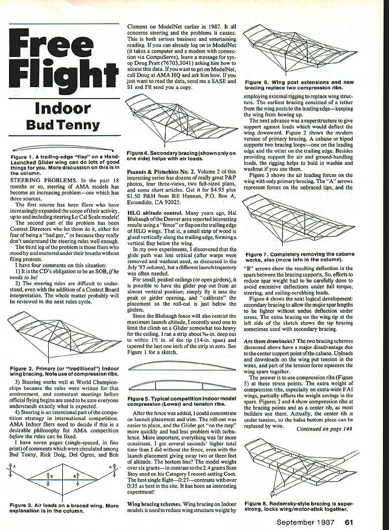
Wing bracing schemes
Wing bracing on indoor models is used to reduce wing structure weight by employing external rigging to replace wing structure. The earliest bracing consisted of a tether from the wing posts to the leading edge — keeping the wing from bowing up. The next advance was a superstructure to give support against loads which would deflect the wing downward. The modern version of primary bracing uses a cabane or bipod supporting two bracing loops — one on the leading edge and the other on the trailing edge. Besides providing support for air and ground-handling loads, the rigging helps hold in wash-in and washout.
Air loading forces on the wing with only primary bracing show the resulting deflection in the spars between the bracing supports. So, efforts to reduce spar weight had to be carefully done to avoid excessive deflections under full torque, steering, and ceiling-scrubbing loads.
The answer is to use compression ribs at these stress points. The extra weight of compression ribs, especially on extra-wide FAI wings, partially offsets the weight savings in the spars. Compression ribs are used at the bracing points and as a center rib, as most builders use them. Actually, the center rib is under tension, so the balsa bottom piece can be replaced by wire.
Are there drawbacks? The two bracing schemes discussed above have a major disadvantage due to the center support point of the cabane. Uploads and downloads at the wing tip put tension in the wires, and part of the tension force squeezes the wing spars together.
What next?
Figure 6 shows the next development. Primary bracing still supports the wings at the tip above the spar. By extending the wing posts above the spar, the leading edge, trailing edge, and tip bracing work off the wing posts. The result is a much stiffer wing which has light spars and needs only two compression ribs. This bracing scheme gives rise to the comment, "If I turn a fly loose inside the bracing and he gets away, I must have forgotten some wires!"
That's still too heavy! The scheme shown in Figure 7, when used with stiff posts and very careful tensioning in the wires, gets rid of the cabane and the last two compression ribs. The wing has two weaknesses:
- It is sort of loose and floppy when you move it by one wing post (as you must when you're mounting the wing).
- Tip collisions with building structure make the wing twist, which isn't all bad. The direction of twist washes out the tip opposite the contact point. This helps that tip to drop, turning the model away from the obstacle.
The ultimate! Well, maybe not — but I like it. The scheme shown in Figure 8 is a close copy of one of dozens Erv Rodemsky has done. It is an integrated wing/motor-stick bracing and is extraordinarily effective. The "Y" wing posts, forming a triangular structure, are a little higher than the really stiff wing posts, and the ribs at the top of the "Y" are tension ribs. But the same wires which form the tension braces extend forward to hook into the thrust bearing and rearward to hook into the rear hook.
Note that the fuselage wires don't have to be thick to adequately brace the fuselage. When the motor is hooked up, the stick bends slightly, and the wing and motor stick are locked into a rigid structure. The high angle of the wires and the separation between them give a lot of strength and torsional support to the motor stick.
I even had a motor stick start to collapse — tuck under — in high humidity, and I was able to grab the prop shaft and thrust bearing and straighten out the stick by working against the top bracing. With help in unhooking the motor, I saved the whole model; whereas I might have lost it without the added support from the top bracing.
That's all. I hope that you, the editor, will be able to fit this whole column in! There are dozens of loose ends, but keep these sketches in mind for future comments which will tie them together.
Bud Tenny P.O. Box 545, Richardson, TX 75080.
Transcribed from original scans by AI. Minor OCR errors may remain.

