
Free Flight: Indoor
Bud Tenny Box 545 Richardson, TX 75080
New newsletter
One of the longest-lasting free-flight clubs in the nation (founded in 1936), the Brooklyn Sky-Scrapers, has finally begun to publish a newsletter. Called Flyoff, it is currently a quarterly publication. It is intended to supplement rather than compete with other magazines and newsletters that cover free-flight model activity. The first issue contained eight pages of model plans, comments, and introductory material on slick paper. The typeset format was fully professional in every respect—very impressive.
The staff (editor Bob Hatschek, assisted by Lydia and Joe Wagner and Bill Colish) promises that technological content will get most of the available space in future issues. The price is $2 per issue in the U.S., and $3 per issue for foreign subscribers (minimum subscription is five issues). Payment must be made in U.S. funds, drawn on a U.S. bank, and payable to "Brooklyn Sky-Scrapers." Send all correspondence to FLYOFF, c/o Robert Hatschek, 316 Grosvenor St., Douglaston, NY 11363.
NFFS Free Flight Hall of Fame
Two indoor pioneers were honored by the National Free Flight Society this year: Frank Cummings and Walter Erbach. Frank is one of the all-time top fliers, with superbly crafted and flown models, but has been largely inactive since the 1966 World Championships in Debrecen, Hungary. Walt Erbach has supported indoor flying with active participation for many years and has a very creative imagination. In recent years his efforts have been concentrated toward developing ornithopters, and he led the way in the recent upsurge in ornithopter activity and performance.
DAIMAA model kitted
For three years, the Denver Area Indoor Model Airplane Association (DAIMAA) has been doing public service at the University of Colorado. This consists of special building classes for aerospace engineering freshmen, followed by competition for the finished aircraft. In return, DAIMAA is allowed to use the Balch Field House (40-ft. ceiling) for their indoor contests.
The kit used for these classes is the P-24 Condor, from Mace Model Aircraft Company, 359 South 119th East Ave., Tulsa, OK 74128 (telephone 918-437-5490). It is specially engineered as a kit to be built by totally inexperienced persons with a minimum of supervision. The plans carry fully detailed instructions, which are profusely and expertly illustrated. Critical dimensions, assembly alignment, and other "sticky" details are handled using jigs and fixtures furnished in the kit.
The bottom line is that seven of the 80-plus models built in the September 1987 session flew over two minutes in Balch Field House. That's not bad for models covered with Japanese tissue and using relatively tiny plastic props!
The P-24 Condor kit is an outstanding "next step" to follow the AMA Cub, and should be considered by any club trying to build up activity and/or train new builders.
Easy B advancement
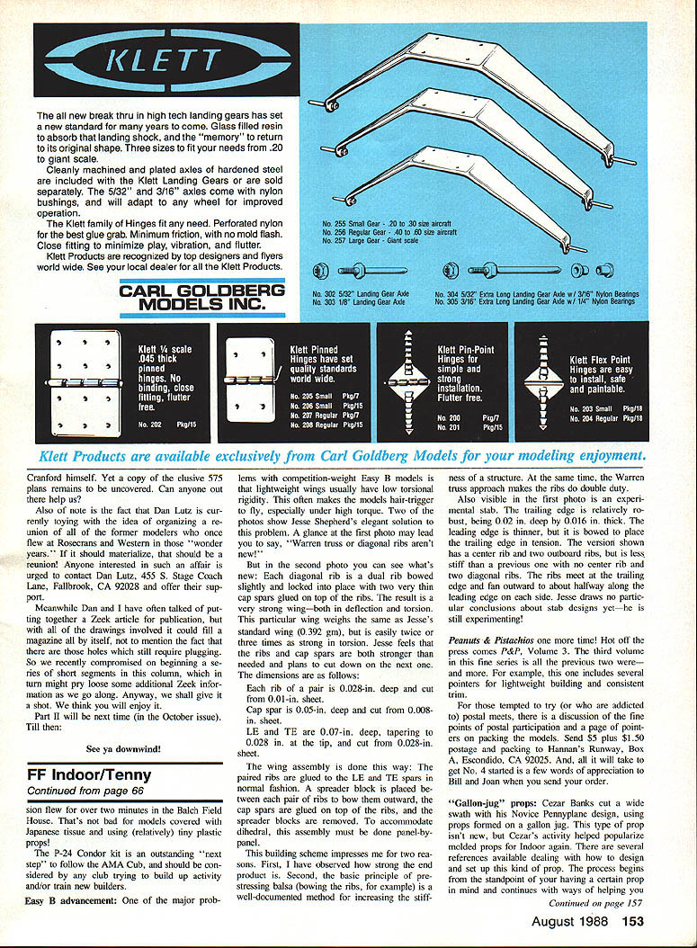
One of the major problems of competition-weight Easy B models is that lightweight wings usually have low torsional rigidity. This often makes the models hair-trigger to fly, especially under high torque. Jesse Shepherd's elegant solution addresses this problem.
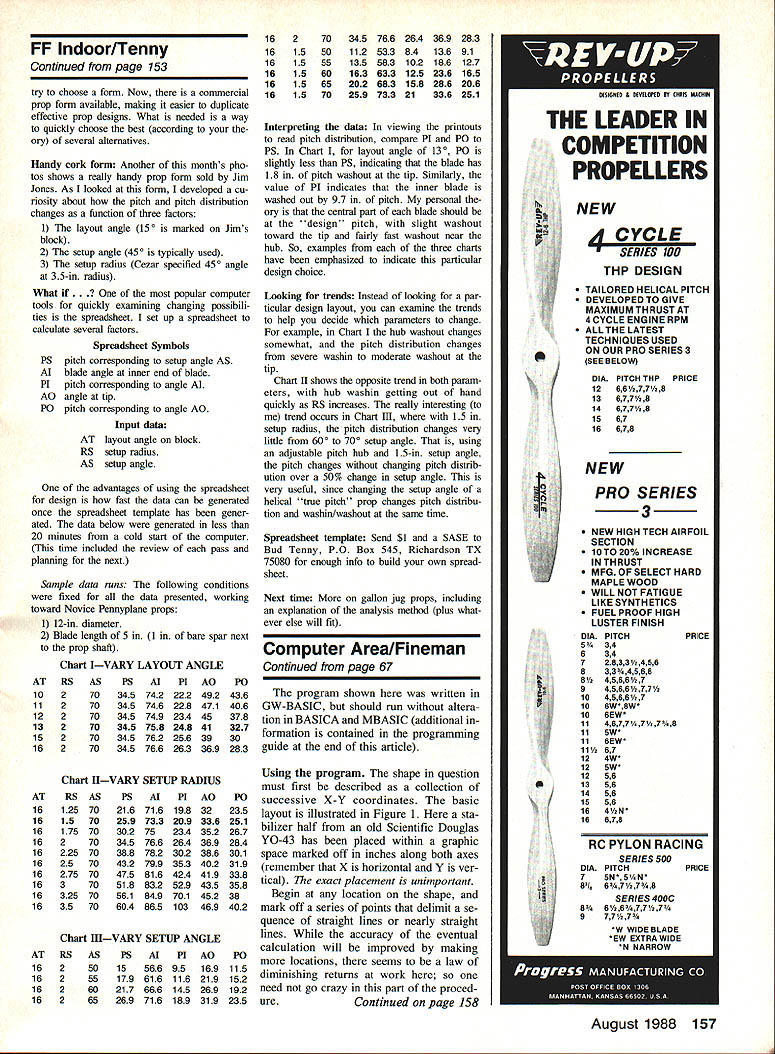
A glance at the first photo may lead you to say, "Warren truss or diagonal ribs aren't new." But in the second photo you can see what's new. Each diagonal rib is a dual rib bowed slightly and locked into place with two very thin cap spars glued on top of the ribs. The result is a very strong wing—both in deflection and torsion. This particular wing weighs the same as Jesse's standard wing (0.392 oz), but is easily twice or three times as strong in torsion. Jesse feels that the ribs and spars are both stronger than needed and plans to reduce them on the next build.
Dimensions:
- Each rib of a pair: 0.028 in. deep, cut from 0.010-in. sheet.
- Cap spar: 0.050 in. deep, cut from 0.008-in. sheet.
- Leading edge (LE) and trailing edge (TE): 0.070 in. deep, tapering to 0.028 in. at the tip, cut from 0.028-in. sheet.
Wing assembly:
- Glue the panel to the LE and TE spars in the normal fashion.
- Place a spreader block between each pair of ribs to bow them outward.
- Glue the cap spars on top of the bowed ribs, then remove the spreader blocks.
- To accommodate dihedral, assemble panel-by-panel.
This building scheme is impressive for two reasons. First, the end product is very strong. Second, the basic principle of pre-stressing balsa (bowing the ribs, for example) is a well-documented method for increasing structural stiffness. At the same time, the Warren-truss approach makes the ribs do double duty.
Also visible in the first photo is an experimental stab. The trailing edge is relatively robust, being 0.002 in. deep by 0.016 in. thick. The leading edge is thinner, but it is bowed to place the trailing edge in tension. The version shown has a center rib and two outboard ribs, but is less stiff than a previous one with no center rib and two diagonal ribs. The ribs are not at the trailing edge and fan outward to about halfway along the leading edge on each side. Jesse draws no particular conclusions about stab designs yet—he is still experimenting.
Peanuts & Pistachios once more!
Hot off the press comes P&P, Volume 3. The third volume in this fine series is all the previous two were and more. For example, this one includes several pointers for lightweight building and consistent trim.
For those tempted to try (or who are addicted to) postal meets, there is a discussion of the fine points of postal participation and a page of point-scoring and the models. Send $5 plus $1.50 postage and packing to Hannan's Runway, Box A, Escondido, CA 92025. And all it will take to get No. 4 started is a few words of appreciation to Bill and Joan when you send your order.
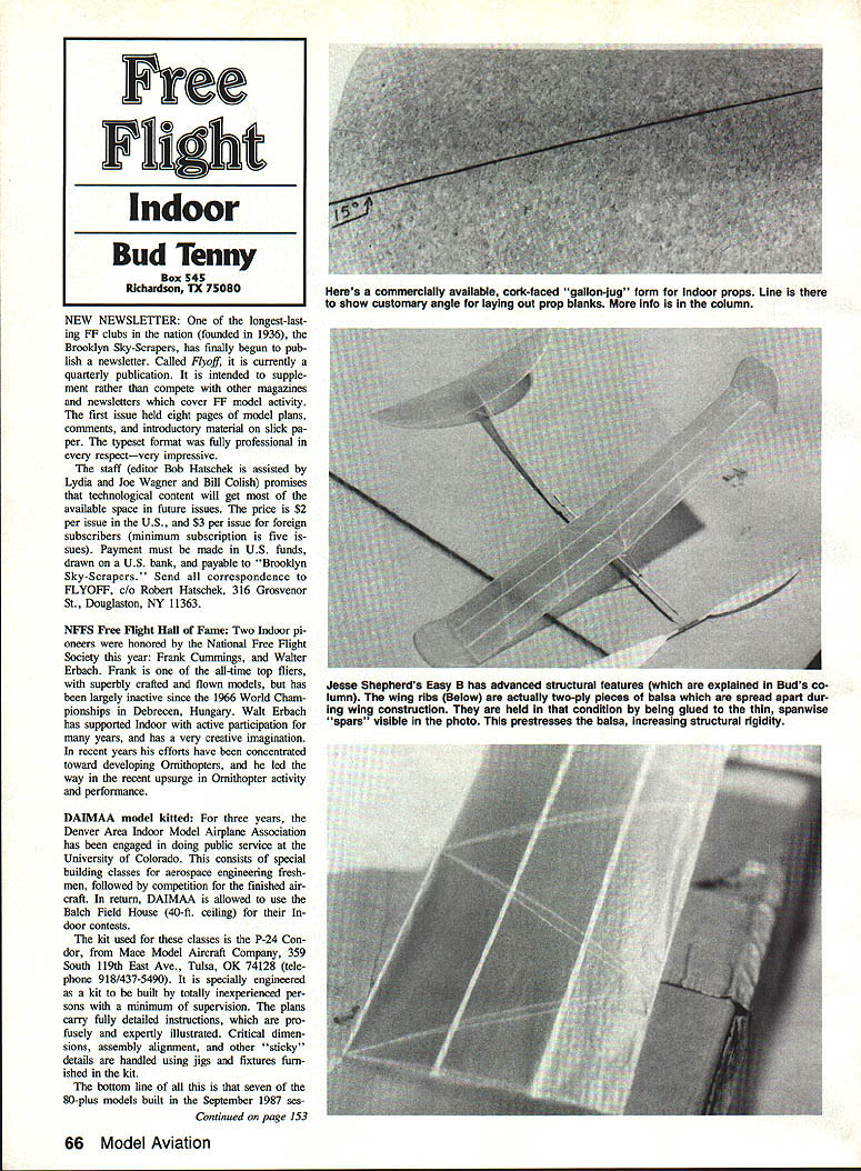
"Gallon-jug" props
Cezar Banks cut a wide swath with his Novice Pennyriders design, using props formed on a gallon jug. The type of prop isn't new, but Cezar's activity helped popularize molded props for indoor flying again. There are several references available dealing with how to design and set up this kind of prop. The process begins from the standpoint of having a certain prop in mind and continues with ways of choosing a form. Now, there is a commercial prop form available, making it easier to duplicate effective prop designs. What is needed is a way to quickly choose the best (according to your theory) of several alternatives.
Handy cork form
Another of this month's photos shows a really handy prop form sold by Jim Jones. As I looked at this form, I developed a curiosity about how the pitch and pitch distribution change as a function of three factors:
- the layout angle (AT; 15° is marked on Jim's block),
- the setup angle (AS; 45° is typically used),
- the setup radius (RS; Cezar specified 45° angle at 3.5-in. radius).
One of the most popular computer tools for quickly examining changing possibilities is the spreadsheet. I set up a spreadsheet to calculate several factors.
Spreadsheet Symbols
- PS — pitch corresponding to setup angle AS.
- AI — blade angle at inner end of blade.
- PI — pitch corresponding to angle AI.
- AO — angle at tip.
- PO — pitch corresponding to angle AO.
Input data:
- AT — layout angle on block.
- RS — setup radius.
- AS — setup angle.
One advantage of using the spreadsheet for design is how fast data can be generated once the template is made. The data below were generated in less than 20 minutes from a cold start of the computer (this time included review of each pass and planning for the next).
Sample data runs
The following conditions were fixed for all the data presented, working toward Novice Pennyrplane props:
- 12-in. diameter.
- Blade length of 5 in. (1 in. of bare spar next to the prop shaft).
Chart I — VARY LAYOUT ANGLE AT RS AS PS AI PI AO PO 10 2 70 34.5 74.2 22.2 49.2 43.6 11 2 70 34.5 74.6 22.8 47.7 40.6 12 2 70 34.5 75.4 24.3 45.2 37.7 13 2 70 34.5 75.8 24.8 42.1 32.7 14 2 70 34.5 76.5 25.8 39.6 31.9 15 2 70 34.5 76.6 26.3 36.9 28.3 16 2 70 34.5 76.6 26.4 36.9 28.3
Chart II — VARY SETUP RADIUS AT RS AS PS AI PI AO PO 16 1.25 70 21.6 71.6 19.8 32.0 23.5 16 1.5 70 25.0 73.5 23.4 35.2 26.1 16 1.75 70 30.4 75.8 28.6 38.6 29.4 16 2 70 34.5 76.6 26.4 36.9 28.3 16 2.25 70 39.5 78.3 33.6 40.2 32.5 16 2.5 70 44.5 80.1 34.8 41.8 33.7
Chart III — VARY SETUP ANGLE AT RS AS PS AI PI AO PO 16 2 60 25.9 78.3 21.3 33.6 25.1 16 2 65 29.0 79.8 23.8 35.8 26.9 16 2 70 34.5 76.6 26.4 36.9 28.3
Interpreting the data
To read pitch distribution, compare PI and PO values. In Chart I, for layout angle of 13°, PO is slightly less than PS, indicating that the blade has 1.8 in. of pitch washout at the tip. Similarly, the value of PI indicates that the inner blade is washed out by 9.7 in. of pitch. My personal theory is that the central part of each blade should be at the "design" pitch, with slight washout toward the tip and fairly fast washout near the hub. Examples from each chart have been emphasized to indicate this particular design choice.
Looking for trends
Instead of looking for a particular design layout, examine the trends to help decide which parameters to change. For example, in Chart I the hub washout changes somewhat and the pitch distribution changes from severe washout to moderate washout at the tip.
Chart II shows the opposite trend in both parameters, with hub washout increasing quickly as RS increases. The interesting trend occurs in Chart III, where with a 1.5-in. setup radius the pitch distribution changes very little from 60° to 70° setup angle. That is, using an adjustable-pitch hub and 1.5-in. setup radius, the pitch changes without changing the pitch distribution over a 50% change in setup angle. This is useful, since changing the setup angle of a "true pitch" prop changes pitch distribution and wash-in/washout at the same time.
Spreadsheet template
Send $1 and a SASE to Bud Tenny, P.O. Box 545, Richardson, TX 75080 for enough information to build your own spreadsheet.
Next time
More on gallon-jug props, including an explanation of the analysis method (plus whatever else will fit).
Transcribed from original scans by AI. Minor OCR errors may remain.

