
Free Flight: Indoor
Bud Tenny Box 545 Richardson, TX 75080
More follow-up
My February 1988 column had a picture of a prop made with a carbon-fiber prop shaft for which I had lost the information as to its designer/maker. Ultimately, Keith Fulmer claimed the prop design and showed another such prop on an experimental-design Bostonian using a carbon-fiber pusher prop.
Further clarification: the model was a Planarian (September 1987 MA) by Barnaby Wajnfan. Keith's contribution lies in making experimental modifications to the design. Barnaby says, from the picture, it appears that Keith did a far better job of building the model than I did on the original. Keith's carbon-fiber prop is a neat idea.
Flyoff newsletter — Part II
Flyoff, announced in the August column and edited by Bob Hatschek, is now off and running with the second issue in hand. It shows two major changes: less introductory material to allow more FF coverage, and a shift to less expensive paper. In case the paper change upsets any subscriber, Bob has offered to refund his money.
As publication continues there will be more changes in appearance. The first two issues were done on professional equipment at greater cost. Production will be shifted to desktop publishing software running on a Macintosh computer, which will allow Bob to tailor style versus cost as necessary. Meanwhile the quality of the content will doubtless improve over the already high level.
Bob is soliciting technical articles for upcoming issues. Potential authors should follow these guidelines:
- Typed, double-spaced, with about 64 characters maximum per line; computer word-processing or normal printer output also acceptable.
- Include all necessary dimensions or an accurate scale. Black-and-white photos are preferred.
- Drawings may be ink, pencil, or good computer graphics (neat, workmanlike, and usable), preferably in a 7 x 10 in. format; absolute maximum size 11 x 17.
In the near future, material submitted on Macintosh disks will be acceptable, and shortly thereafter it will be possible to submit articles by modem. Flyoff is published quarterly at $2 per issue in the U.S., and $3 per issue for foreign subscribers (minimum subscription five issues). Payment must be made in U.S. funds, drawn on a U.S. bank, and payable to "Brooklyn Sky-Scrapers." Send all correspondence to Flyoff, c/o Robert Hatschek, 316 Grosvenor Street, Douglaston, NY 11363.
More on "gallon-jug" props
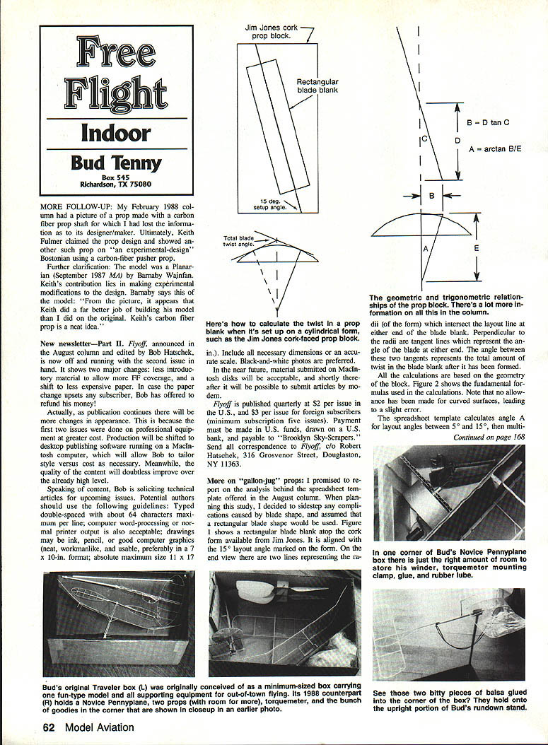
I promised to report on the analysis behind the spreadsheet template offered in the August column. When planning this study, I decided to sidestep any complications caused by blade shape and assumed a rectangular blade shape would be used. Figure 1 shows a rectangular blade blank atop the cork form available from Jim Jones. It is aligned with the 15° layout angle marked on the form.
On the end view there are two lines representing the radii which intersect the layout line at either end of the blade blank. Perpendicular to the radii are tangent lines which represent the angle of the blade at either end. The angle between these two tangents represents the total amount of twist the blade blank has after it has been formed.
All of the calculations are based on the geometry of the block. Figure 2 shows the fundamental formulas used in the calculations. Note that no allowance has been made for curved surfaces, leading to a slight error. The spreadsheet template calculates angle A for layout angles between 5° and 15°, then multiplies it by two to get the twist for the whole blade. The "what if" part of the template then calculates the tables shown in the previous column (August 1988 MA).
Constants in the template assume the block is 7.8 in. long, which is irrelevant as long as your blade segment is shorter than that. The assumed block radius corresponds to the Jones block (3.1 in.). If the block or form you use is different, change the constants in the formulas. Also, constants assume a 5-in. blade segment and 12-in. prop diameter. You specify layout angle, setup angle, and setup radius, and the spreadsheet makes the calculations.
BASIC program and spreadsheet
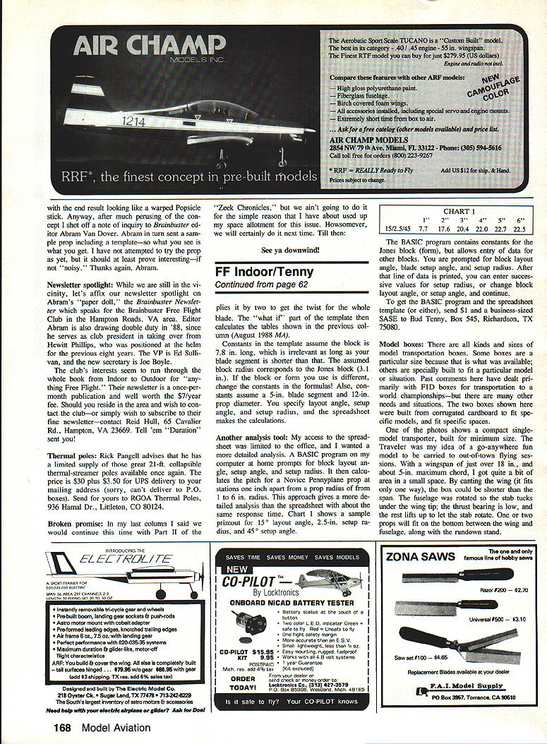
My access to the spreadsheet was limited to the office, and I wanted a more detailed analysis. A BASIC program on my computer at home prompts for block layout angle, setup angle, and setup radius. It then calculates the pitch for a Novice Pennyplane prop and prints the pitch for each part from a radius of 1 to 6 in. in 1/2-in. steps. This approach gives a more detailed analysis than the spreadsheet, with about the same response time. Chart 1 shows a sample printout for 15° layout angle, 2.5-in. setup radius, and 45° setup angle.
The BASIC program contains constants for the Jones block (form), but allows entry of data for other blocks. You are prompted for block layout angle, blade setup angle, and setup radius. After the line of data is printed, you can enter successive values for setup radius, or change block layout angle, or setup angle, and continue.
To get the BASIC program and the spreadsheet template (or either), send $1 and a business-size SASE to Bud Tenny, Box 545, Richardson, TX 75080.
Model boxes
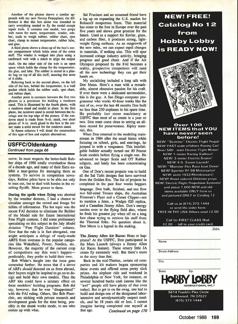
There are all kinds and sizes of model transportation boxes. Some boxes are of particular size because that is what was available; others are specially built to fit a particular model or situation. Past comments here have dealt primarily with F/F boxes for transportation to a world championship—but there are many other needs and situations. The two boxes shown in the photos were built from corrugated cardboard to fit specific models; the results are described below.
One photo shows a compact single-tray transporter, built for minimum size. The Traveler was my idea of a go-anywhere fun model to be carried to out-of-town flying sessions. With a wingspan of just over 18 in. and about 5 in. maximum chord, it will fit into a small space. By canting the wing, the span will fit the box; the fuselage was rotated so the stab tucks under the wing. The fuselage was built in the usual box fashion, with a small removable panel to allow access to the wing and fuselage, along with the rundown stand. One or two props will fit in the bottom between the wing and fuselage, along with the rundown stand.
Another photo shows a similar approach with my new Novice Pennyplane; the difference is that this box alone was intended to carry everything needed to fly the model except repair tools. It contains one model, two props with room for more, and the following items:
- Torquemeter
- Winder
- Rubber
- Scale to weigh rubber
- Rubber chart
- RPM chart
- Clamp to mount torquemeter
- Rubber lube
- Glue
A third photo shows a close-up of the box's corner compartment which holds most of the extra stuff. The winder is wedged into place using a cardboard wedge with a notch to align the output shaft. On the other side of the box is an open space which holds the clamp for the torquemeter, the glue, and lube. The rubber is stored in a plastic bag on top of all this stuff, assuring that none of it shifts.
Referring back to the second photo, on the left side of the box, behind the torquemeter, is a wall pocket which holds the rubber scale, RPM chart, and rubber chart.
Both boxes provide a provision for holding a rundown stand. This is illustrated by another photo showing a rundown stand and model in place. In the first photo, the rundown stand is stored between the fuselage and the top edge of the picture. If the rundown stand is made from 1/4-in. stock, two short pieces of 1/4-in. stock glued to the box in the corner make a solid mount for the rundown stand.
In future columns I will detail the construction of this type of box and explain alternatives.
Transcribed from original scans by AI. Minor OCR errors may remain.

