
Free Flight: Indoor
Byline
Bud Tenny Box 545 Richardson, TX 75080
USIC Schedules
Most of you planning to attend the 1991 USIC/AMA Nationals at Johnson City have received and returned entry blanks containing an event schedule. Please be advised that the Ornithopter and Federation ROG events have been rescheduled in the interests of better model safety.
FROG Rules
At the request of CD Tony Italiano, some changes have been made in the Federation ROG rules. The following restriction has been added: "The length of the model from the front of the propeller to the rearmost part must not be greater than 18 inches." Note that these rules are only official at the USIC, unless adopted by other CDs and announced in advance of the contest. The originating group for FROG, the Delaware Valley Federation of Model Airplane Clubs, has announced that the original rules shall continue.
The list of official records is maintained by members of that group. The current top recorded time is still held by Jim Clem at 9:41, from a flight made at Lakehurst at the 1990 Labor Day sessions.
MiniStick Postals
Tom Vallee's MiniStick event continues to grow in popularity. Several indoor newsletters have published one or more plans for these models, and the competition has become international in scope. Model airplane clubs in Japan and England are participating in a postal challenge with Tom's club. The MiniStick rules are not restrictive; the event becomes a one-design event, and it is expected that the performance of these tiny models will soon exceed current expectations.
Rubber Lubricants: Armorall and Son of a Gun
The product Armorall, sold as a protectant for plastic parts, has been used quite successfully as a rubber lube for indoor models. Scale model fliers like it because it splatters less than other rubber lubes. A similar product, Son of a Gun, is now reported to be superior to Armorall by those who have tried both.
Flying Opportunities
Here is the new information available. CDs please fill in dates for after June 1991 and beyond. Refer to the January 1991 column for the list of site contact persons. Be safe: check contest status by phone before leaving home!
- Idaho: Kibbie Dome (Moscow) — Tagliafico has set up a 3-day contest in the Kibbie Dome, Aug. 8-11, 1991. Call or write Andy at 650-B Taybin Rd. NW, Salem, OR 97304; 503/371-0492 for more details.
- Maryland: Goddard NAS record trials and flying sessions are scheduled in the auditorium of Building 8 at Goddard NAS on Saturdays, 11 a.m. to 10:30 p.m.: June 22, July 13, July 27, Aug. 10, Aug. 24, Sep. 14, Sep. 28, Oct. 12, Oct. 26 and Nov. 9, 1990. All sessions beginning with Aug. 24 will be sanctioned as AMA and FAI record trials. NASA security requires that attendees be U.S. citizens and AMA members, with license available for inspection at the gate and names on a list.
Tell Tom of your intention to attend in advance of each meet. Changes in NASA launch schedule and other possible events can pre-empt the auditorium without much warning. Be sure to verify the date with Tom before leaving home! Tom Vallee, 444 Henryton So., Laurel MD 20707; 301/498-0790.
Supplies and Services
- Old Timer Model Supply: New catalog out — $2. OTMS, P.O. Box 7334, Van Nuys, CA 91409.
- Gene Hempel: Custom engine work, including chrome plating; has special Cox .049-.051 parts. 301 North Yale Drive, Garland, TX 75042; Tel 214/272-5210.
- Dave Haught: Many plans for rubber and CO2 scale models from the early days of aviation. He has just sent to the printer a new book, "Building with Kids," with over 20 plans and ideas for teaching youngsters model building. The book will be $20 postpaid. Send a SASE to Haught Graphics, Rt. 1, Box 978, Munising, MI 49862 for the list of plans.
- Best-by-Test Model Company plans: Plans for the rubber model (and a towline glider) kits from the old (1938–48) Best-by-Test Model Company can be purchased from the designer Edward Schlosser, P.O. Box 412, Ridgefield, NJ 07657-1418. He also has hardware of interest to rubber fliers — thrust washers, tension springs, a 14-inch machine-carved balsa propeller, etc. A SASE should get you catalog sheets showing a copy of an old ad with general arrangement drawings of the models.
Notes: The Altimeter and Stratometer have been popular recently in SAM small cabin and stick events. The larger 44-in. span Enduro (stick) and Sensatherm (cabin) should become popular as they are light, structurally simple, and well-designed for duration events.
Free Flight: Indoor (continued)
Indoor Model Stability
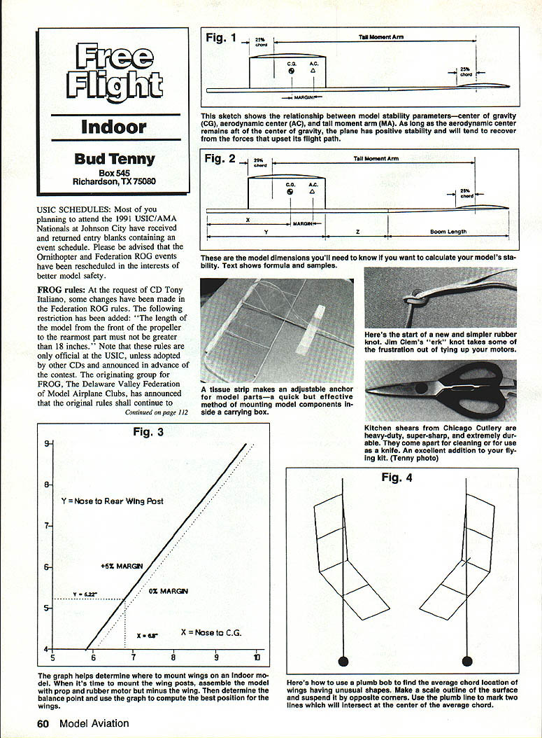
The October 1990 column began a discussion of stability and stability margin. The sketch in that column shows the relationship between center of gravity (CG), aerodynamic center (AC) and tail moment arm (MA). The definition of MA is the distance between the 25% chord points on the wing and stabilizer. The distance between the CG and AC is defined as the margin of stability. As long as the CG is in front of the AC, the model has positive stability; that is, the model tends to recover from forces that upset the flight path.
If the CG and AC are at the same distance from the nose, the model is neutrally stable and will not try to recover; with the AC in front, the model will tend to increase the upset. In the December 1947 Air Trails, Hank Cole published an article, "The Center of Gravity Question," which gave a full explanation of aircraft stability. Many years later, Charlie Sotich suggested applying Hank's ideas to indoor models.
Hank's article covered more factors than will be discussed here, but indoor fliers can greatly benefit from a simplified application of his principles. Hank summarized his design ideas in a graph that allows determination of a correction factor (Cf) specific to a particular model design. Charlie's suggestion developed into a graphic approach for locating indoor model wing sockets for best performance. For almost any indoor model design it is possible to locate the wing sockets correctly before the first flight. The critical factors are wing and stabilizer aspect ratios, AC, Cf, and the tail moment arm.
Definitions:
- Average chord = span squared divided by area.
- Aspect ratio = projected span divided by average chord.
- CG = balance point of the complete model with motor.
- LE = leading edge.
- R = wing aspect ratio.
- Rt = stabilizer aspect ratio.
- TE = trailing edge.
Hank Cole's graph was computed using this formula: Cf = [0.85 * Rt * (R − 0.5)] / [R * (Rt + 3)]
Hank used this formula to compute the aerodynamic center: AC = (stab area * MA * Cf) / wing area
Example (Easy B model) Assume an Easy B model with:
- Wing: 3 in. chord x 18 in. span (rectangular)
- Stabilizer: 2 in. chord x 12 in. span (rectangular)
- Motor stick: 11 in.
- Tail boom: 1 in.
- Wing leading edge: 4 in. from the nose
- Model balance (CG): 6 in. from the nose
Compute values:
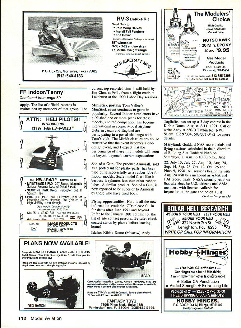
- X = 6 in. (balance point)
- Y = 7 in.
- Z = 4 in.
- R = wing aspect ratio = 18 / 3 = 6
- Rt = stab aspect ratio = 12 / 2 = 6
- Wing area = 54 sq. in.
- Stab area = 24 sq. in.
- Cf = 0.85 * 6 * (6 − 0.5) / [6 * (6 + 3)] = 0.519
Compute AC:
- From the wing TE, the 25% wing chord point is 0.75 x 3 in. = 2.25 in. behind the leading edge.
- MA = 2.25 in. + Z (4 in.) + 11 in. (boom length) − (0.75 * 2 in.) = 15.75 in.
- AC = (24 * 15.75 * 0.519) / 54 = 3.63 in. behind the 25% wing chord.
Margin:
- CG relative to the 25% wing chord point is 2.25 in. behind it.
- Margin = AC − CG = 3.63 − 2.25 = 1.38 in.
- Expressed as % of wing chord: 1.38 / 3 = 46%.
Experience shows that a margin of about 5% (0.15 in. for a 3 in. chord) is optimum for most indoor models.
Graphic solution and wing placement The graphic solution assumes an initial stability margin of 0% so that CG and AC are both X in. from the nose. To illustrate wing location effects, compute AC for two wing locations, wings at 2 in. and 6 in. from the nose:
- Case 1 (wing LE = 2 in.): Z = 6 in., Y = 5 in.
- AC = (24 * 17.75 * 0.519) ÷ 54 = 4.09 in. behind 25% wing chord.
- AC location from the nose = 5 in. − 2.25 in. + 4.09 in. = 6.84 in. from the nose.
- Case 2 (wing LE = 6 in.): Z = 2 in., Y = 9 in.
- AC = (24 * 13.75 * 0.519) ÷ 54 = 3.17 in. behind 25% wing chord.
- AC location from the nose = 9 in. − 2.25 in. + 3.17 in. = 9.92 in. from the nose.
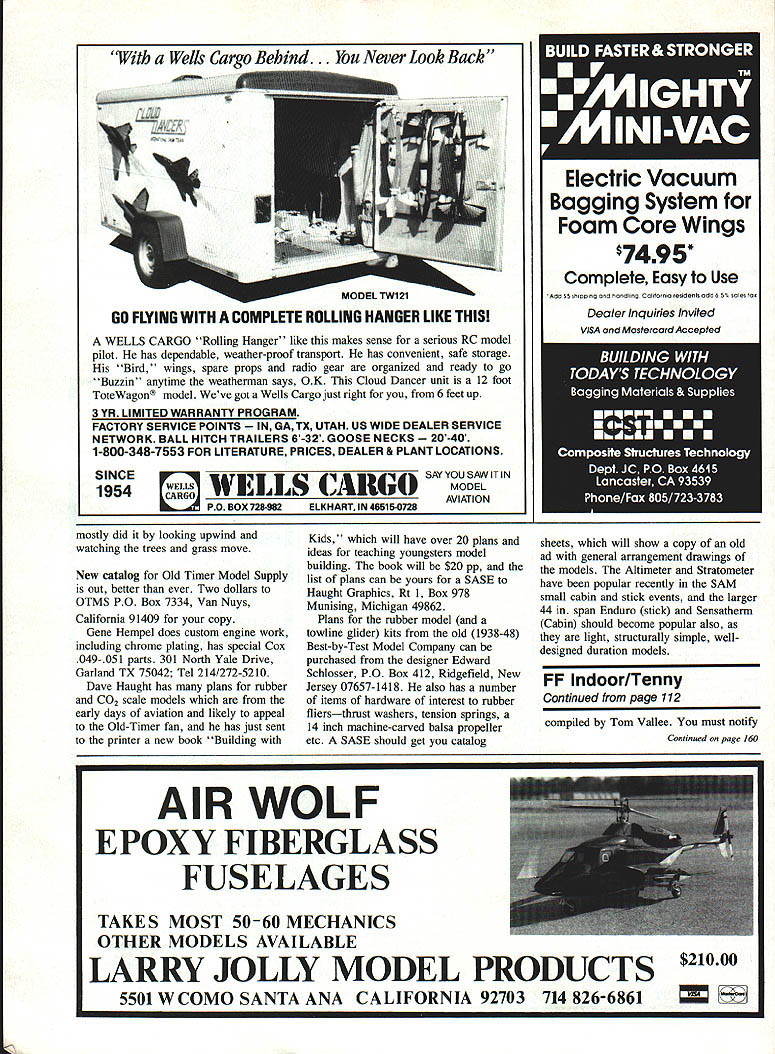
Plotting these computed data produces a dotted line labeled "0% Margin." Since 0% margin is unacceptable, a heavy line marked "+5% Margin" is added to the graph. When it is time to mount the wing posts, assemble the model with prop and rubber motor but without the wing, and determine the balance point.
For our example, assume the balance point is 6.8 in. from the nose. Draw a vertical line from 6.8 on the graph to the 5% margin line, then a horizontal line from that intersection to the left edge of the graph. This line intersects the ordinate at 5.22 in., showing the rear post should be 5.22 in. from the nose. However, this result places the wing ahead of the balance point; the assembled model won't balance where the first test indicated.
To correct this, attach a weight equal to the wing weight at one-half chord ahead of the 5.22 in. point and do a new balance. The graphic solution from this test should give a good location for the rear post. Note that a second balance test should be made if the computed wing position is not centered over the balance point.
Average chord for non-rectangular surfaces The stability margin example above was simplified by having constant-chord wing and stab. Finding the average chord is easy if the wing or stab outline is symmetrical, but surfaces with sweepback or non-symmetrical taper are more difficult to analyze.
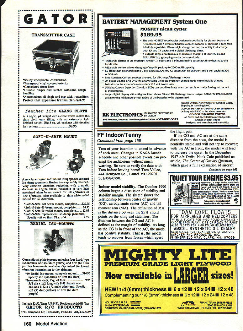
Perhaps the easiest method for finding the average chord of an oddly shaped surface is to make a scale outline of the surface and suspend it by opposite corners. Be sure the outline is free to pivot easily so that the centroid will hang directly below the pivot point. A plumb line can then be used to locate the average chord relative to the nose. A similar method can be used for the stabilizer. Note that for highly swept or tapered surfaces the average chord may lie outside the outline area and be difficult to determine by the suspend-from-corners method. In that case, mark two lines that will intersect at the center of the average chord; use that chord location to compute wing placement.
While this method of model balance may seem complicated, it has been used successfully since the early 1970s. The only time it has failed was when the second balance test (to correct for wing weight) was omitted.
The Erk Knot
Indoor flying thrives on rubber knots — everyone has a favorite method of tying motors. The problem is delicate: an elaborate knot adds unnecessary weight; scuffing the rubber during tying can weaken it; if the knot doesn't hold you may lose the motor or the flight.
The simplest knot described here was shown by Jim Clem and is called the "erk knot." Start with a simple overhand knot in both strands. Moisten this knot and snug it up almost as tight as possible. Next, coat the outside edge of the knot lightly with the super-thick grade of cyanoacrylate glue and quickly pull the knot tighter. (Jim claims that if you listen closely as you pull, you will hear the "erk" sound.) Examine the motor strands where they exit the inner side of the knot; if any glue shows there, you used too much.
To finish the knot, trim the ends to about 1/8 in. and glue them together. This knot works well on both tan and Pirelli rubber. It is potentially the lightest knot and uses less rubber than many other knots.
Super Shears and Small-Box Mounting
- Super shears: A recommended tool is heavy-duty kitchen shears (Chicago Cutlery). These are super-sharp, durable, and come apart for cleaning; they can also be used as a knife. In Dallas they are available from Dillard's.
- Mounting components inside a carrying box: A quick method is shown for securing a plug-in Pennyplane stab. Use a strip of tissue glued down at one end to hold the stab against a block; the free end of the tissue is attached with a pressure-sensitive label. The label releases easily, is reusable, and can be quickly replaced when necessary.
Transcribed from original scans by AI. Minor OCR errors may remain.

