

Free Flight
Old-Timer
Clarence Haught
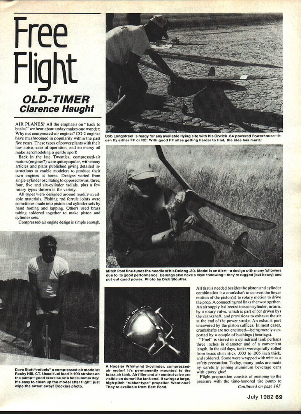
Airplanes? All the emphasis on "back to basics" we hear about today makes one wonder: why not compressed-air engines? CO2 engines have mushroomed in popularity within the past five years. These powerplants, with their low noise, ease of operation, and no messy oil, make aeromodeling a gentle sport.
Back in the late Twenties, compressed-air motors were quite popular, with many articles and plans published giving detailed instructions to enable modelers to produce their own engines at home. Designs varied widely, including:
- single-cylinder oscillating types
- opposed twins
- three-, four-, five- and six-cylinder radials
- a few rotary types for variety
All types were designed around readily available materials. Fishing-rod ferrule joints were sometimes made into piston-and-cylinder sets by hand-honing and lapping. Others used brass tubing soldered together to make piston-and-cylinder sets.
Compressed-air engine design is simple. All that is needed, besides the piston-and-cylinder combination, is a crankshaft to convert the piston's linear motion to rotary motion to drive the prop. A connecting rod links the two. An air supply is directed to each cylinder, in turn, by a rotary valve that is part of (or driven by) the crankshaft, and provisions are made to exhaust the air at the end of the power stroke—an exhaust port uncovered by the piston usually suffices. In most cases crankshafts are not enclosed, being merely supported by a couple of bushings.
"Fuel" is stored in a cylindrical tank perhaps three inches in diameter and of a convenient length. In the old days, tanks were spirally rolled from brass shim stock, .003 to .006 inch thick, and soldered. Some were wrapped with wire as a safety precaution. Today, many tanks are made by carefully joining aluminum beverage cans with epoxy glue.
Flight preparation consists of pumping up the pressure with the time-honored tire pump to something under 100 psi (typically about 100 strokes of the pump). Starting the engine consists of opening the air valve.
If this sounds interesting and you are ready for the challenge of constructing your own compressed-air engine, drop a line to Bert Pond, 128 Warren Terrace, Long Meadow, MA 01106. Bert, "the Dean of Compressed-Air Engines," has plans for over 25 different engines as well as information on tank construction and CA flying in general. Prices are reasonable.
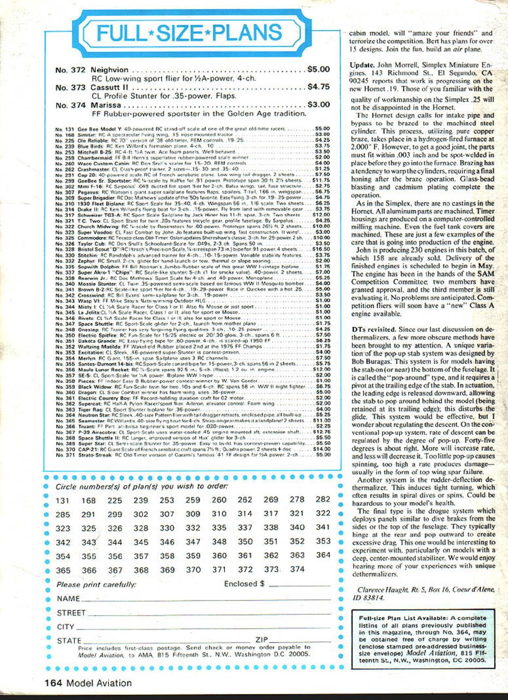
If the thought of all that tinkering, cutting, filing and soldering slows you down, Bert has a limited quantity of the famous Hoosier Whirlwind three-cylinder radials available, complete with tank and ready to hum. The Hoosier Whirlwind has been the engine to beat since 1929 and is popular today in the SAM Champs compressed-air event promoted and sponsored by Tim Banaszak, secretary-treasurer of SAM. This engine, paired up with the Hobart cabin model, will "amaze your friends" and terrorize the competition. Bert also has plans for a variety of other designs. Join the fun—build an airplane.
Update
John Morrell, Simplex Miniature Engines, 143 Richmond St., El Segundo, CA 90245, reports that work is progressing on the new Hornet .19. Those familiar with the quality of workmanship on the Simplex .25 will not be disappointed in the Hornet.
The Hornet design calls for the intake pipe and bypass to be brazed to the machined steel cylinder. This process, utilizing pure-copper braze, takes place in a hydrogen-fired furnace at 2,000°F. To get a good joint, the parts must fit within .003 inch and be spot-welded in place before they go into the furnace. Brazing tends to warp the cylinders, requiring a final honing after the braze operation. Glass-bead peening and cadmium plating complete the work.
As in the Simplex, there are no castings in the Hornet: all aluminum parts are machined. Timer housings are produced on a computer-controlled milling machine. Even the fuel tank covers are machined. These are just a few examples of the care going into production of the engine. John is producing 230 engines in this batch, of which 158 are already sold. Delivery of the remaining engines is scheduled to begin in May. The engine has been in the hands of the SAM Competition Committee; two members have granted approval and the third member is still evaluating it. No problems are anticipated. Competition fliers will soon have a "new" Class A engine available.
DTs revisited
Since our last discussion on dethermalizers (DTs), a few more obscure methods have been brought to my attention.
One unique variation of the pop-up stab system was designed by Bob Buraguss. This system is for models having the stab on (or near) the bottom of the fuselage. It is called the "pop-around" type and requires a pivot at the trailing edge of the stab. In actuation, the leading edge is released downward, allowing the stab to pop around behind the model (being retained at its trailing edge); this disturbs the glide. This system would be effective, but I wonder about regulating the descent. On the conventional pop-up system, rate of descent can be regulated by the degree of pop-up. Forty-five degrees is about right. More will increase the rate; less will decrease it. Too little pop-up causes spinning; too high a rate produces damage—usually wing-spar failure.
Another system is the rudder-deflection dethermalizer. This induces tight turning, which often results in spiral dives or spins and could be hazardous to your model's health.
The final type is the drogue system, which deploys panels similar to dive brakes from the sides or the top of the fuselage. They typically hinge at the rear and pop outward to create excessive drag. This one would be interesting to experiment with, particularly on models with a deep, center-mounted stabilizer.
We would enjoy hearing more of your experiences with unique dethermalizers.
Clarence Haught, Rt. 5, Box 16, Coeur d'Alene, ID 83814.
Transcribed from original scans by AI. Minor OCR errors may remain.

