
Free Flight: Old-Timers
Clarence Haught
Turnabout
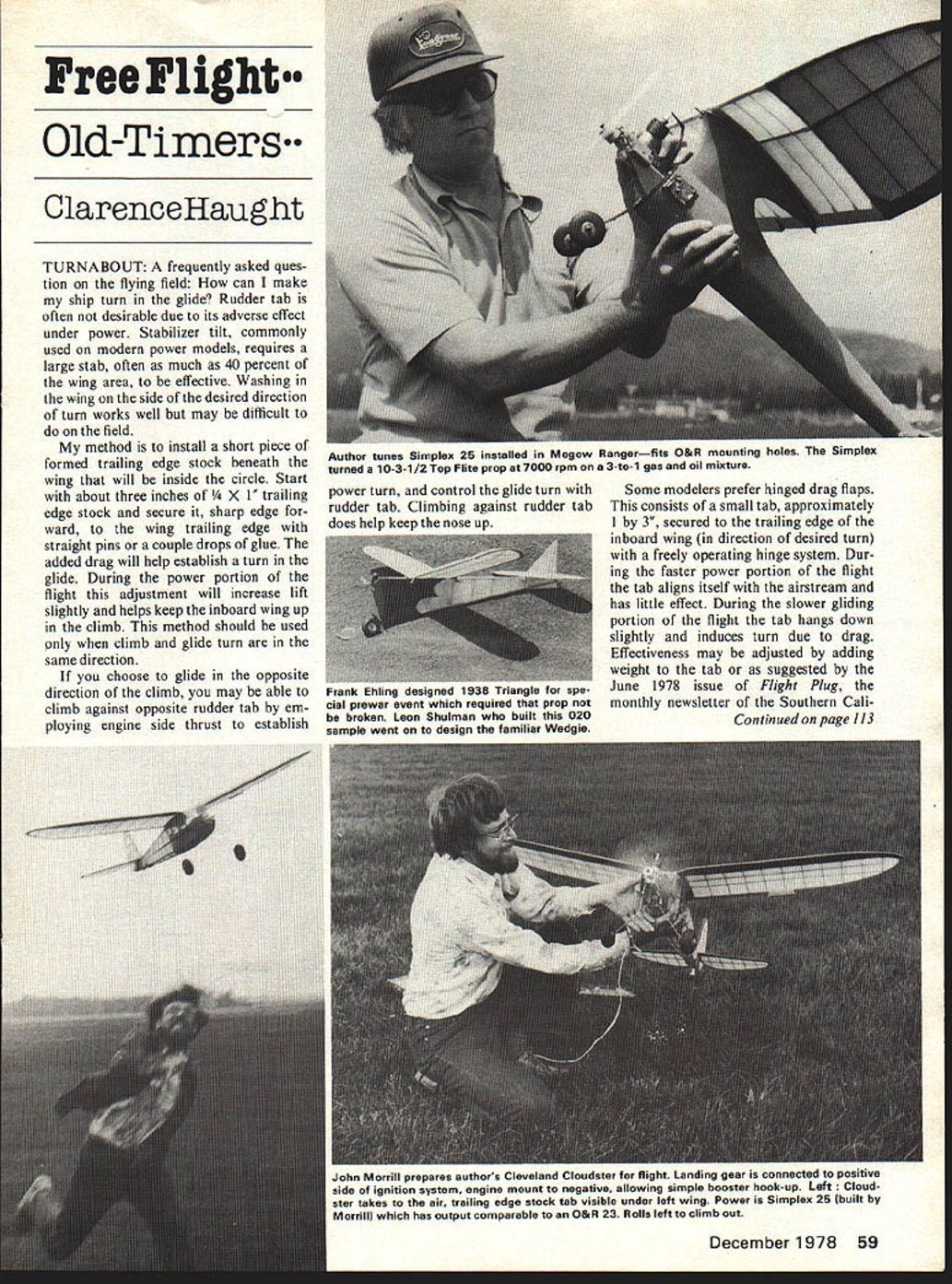
A frequently asked question on the flying field: How can I make my ship turn in the glide? Rudder tab is often not desirable due to its adverse effect under power. Stabilizer tilt, commonly used on modern power models, requires a large stab—often as much as 40 percent of the wing area—to be effective. Washing in the wing on the side of the desired direction of turn works well but may be difficult to do on the field.
My method is to install a short piece of formed trailing-edge stock beneath the wing that will be inside the circle. Start with about three inches of 1/4" x 1/4" trailing-edge stock and secure it, sharp edge forward, to the wing trailing edge with straight pins or a couple of drops of glue. The added drag will help establish a turn in the glide. During the power portion of the flight this adjustment will increase lift slightly and helps keep the inboard wing up in the climb. This method should be used only when climb and glide turn are in the same direction.
If you choose to glide in the opposite direction of the climb, you may be able to climb against opposite rudder tab by employing engine side thrust to establish a power turn, and control the glide turn with rudder tab. Climbing against rudder tab does help keep the nose up.
Some modelers prefer hinged drag flaps. This consists of a small tab, approximately 1" by 3/8", secured to the trailing edge of the inboard wing (in the direction of desired turn) with a freely operating hinge system. During the faster power portion of the flight the tab aligns itself with the airstream and has little effect. During the slower gliding portion the tab hangs down slightly and induces turn due to drag. Effectiveness may be adjusted by adding weight to the tab or, as suggested by the June 1978 issue of Flight Plug, the monthly newsletter of the Southern California Ignition Flyers, which gave us Peanut Scale and Embryo Endurance.
International Free Flight Contest
More serious modelers had their eyes on the first International Free Flight contest held in Woodvale, England this August. To round out the spectrum of free-flight scale events, such a meeting has long been needed. Will it continue and blossom into full recognized status as with the RC and CL events? If it does, it will be thanks to a group of dedicated modelers who put in a great deal of effort organizing, running, and participating in this memorable beginning.
Ranging from Eric Coates' winning superscale DH9a, W. Dennis' daring twin-engined Handley Page H.P. 400 which garnered second, to fine ships which could not make the 30-second qualifying flight, a wide variety of models took part. Terry Manly took home third with a Blackburn Swift. Bill Hannan's fine CO2 Farman Moustique was proxied to fourth, and my MacDonald S-21, the only rubber ship to qualify, was flown to fifth by Joe Barnes, one of Britain's finest rubber fliers. Finishing sixth and last among the qualifiers was D. Hunt's CO2 Comper Swift.
Rumor has it that Canada may be next year's site, so get going on that model now. Don't be scared off by the word international! A good, solid, stable and flyable model has as much chance as a seldom-flown superscale that is more prone to give problems. Total entries numbered under 20 this year, but with more notice and your participation it can succeed in becoming an annual and international official event.
TWA of the Month
"Iron Mike" Midkiff's rubber-powered wheels-up Hellcats are becoming legend. Built from Bill Hannan plans in Flying Scale Models of WWII ($6.95; Bill Hannan, 621 W. 19th St., Costa Mesa, CA 92627), not one but two of Mike's mini-masterpieces have flown away on five- and six-minute flights! The models span 21" and weighed 1.2 oz and 1.4 oz without rubber. The 8½" props (20° pitch) were turned by 24" long motors, one with two loops of 1/8" and one with a loop of 3/16" flat rubber. The models both climbed left and glided right. Mike feels that the design's stability is in part due to the Navy's insistence on good low-speed handling characteristics at the time the Hellcat was in service.
Hints, tips, photos, and TWA's are welcome.
Bill Warner 423-C San Vicente Blvd., Santa Monica, CA 90402
California Ignition Flyers
"A floating drag tab out on the wing can be a useful glide-circle trim method on some OT designs. A couple of its disadvantages, however, are: it's not simple (on the field) to move it in or out along the wing for fine tuning, and it can get knocked off in transporting, or just handling the model."
"SCAMPER: Hugo Lung has solved these problems nicely. He mounts his tabs to the trailing edge with two tiny alligator clips. A piece of wire (1/16" or .045") connects the clips and provides the tab hinge. The wire can be soldered to the clips after sleeving it with aluminum tubing, to which the tab is attached. Or, the wire can be attached directly to the tab and extended through the clips with a washer soldered on each side of each clip to hold the unit together. Simple, functional, neat!"
Speaking of Newsletters
The August issue of the Informer, distributed by the Central Indiana Aeromodelers, has an excellent article by Bob Larsh on the Goldberg Zipper. Editor Harry Murphy will be glad to send the newsletter to you for $3.00 per year. Contact him at 3824 Oakwood Blvd., Anderson, IN 46011.
C.I.A. Informer — O.T. HLG Event
The same issue reported on their O.T. HLG event:
"First-time-ever event, O.T. HLG, drew 16 entries and a variety of designs as well. From the dooryard pages of Zaci Yearbooks and old model mags came some rather unorthodox looking creations, including a couple of twin-tailed weirdos. It was also quite hilarious at times to listen to all the grunts and groans put forth by the 'over-40' gang when attempting a weak-arm heave to the heavens with one of these vintage model designs. One has to admit that HLG designs have also come a long way since the concepts of the '30s... I would say that most progress has been made in recent years. Could it also be said that the Sweepette is the Zipper of HLG? (Someone care to tackle that one? I'm no expert on the subject.) Anyway, it proved to be an interesting diversion, and get 'em ready for next year fellas! You've got all winter to thumb through all those auld mags and books."
What's in a Name
It's interesting to note the names attached to various contests. Here in the Northwest, various clubs have established traditional meets with unusual names: the "Strat O Bats" of Seattle and their "RAG Meet" (rubber and glider), or the Boeing Hawks "Power Bash," an all-power contest with prizes clear to last place based on a six-flight total. "The Misery Meet" held in February under "unusual" weather conditions varying from fog to sunshine with everything in between—this meet is approximately 20 years old. Or how about the "Silents Please" sponsored by the Willamette Model Club of Albany, Oregon, where silence is golden and the loudest sound tolerated is the whoosh of a Jetex or the flap of an unwinding OT rubber ship.
It would be interesting to hear from some of the clubs out there who also have unique names for their contests.
In the Dark About Free Flight?
The USFFC at Taft has offered night flying for several years. Just last year at the "Power Bash" the event was flown for the first time here in the Northwest. Bob Petro of Athol, Idaho, not having an appropriate AMA gas ship, flew his Madewell-powered Clipper in the competition. While somewhat handicapped flying against AMA ships in essentially dead air, it was exciting to hear the old Madewell grinding skyward in the black night air!
Practical tips:
- The chemical lights sold in sporting goods stores can be conveniently banded to the landing gear of your favorite OT ship, or you can rig up a flashlight bulb and dry cell for your "navigation" light.
- Don't hook the light into the ignition circuit and shut off the light when the timer opens the circuit!
- Pick a dark, moonless night for best results. Use plenty of light in the pit area to avoid any accidents.
- Don't forget to light the DT fuse since there can be lift around at night if the ground was heated up during the day and the night is cool.
It's fascinating to see the light and the glow of the DT fuse spiraling upward, and then silence as the engine quits and the light bobs around in the night sky. Try it—it's a great change of pace!
Clarence Haught Rt. 5, Box 16, Coeur d'Alene, ID 83814
Super Burp — Construction and Flying
Strength and Engine Head Mount
The system should be strong enough to easily withstand the required 40-lb AMA pull-test.
Select a rigid piece of material for the engine head mounting bracket. A piece of .060" stainless steel, or any material of equivalent strength, will suffice. Make a pattern representing the shape of the engine head mount presented on the plans. Transfer the shape to the chosen material, saw the general shape with a hacksaw or bandsaw, and finish-shape with a file. Drill the mounting holes to correspond to the holes drilled in the engine head and drill the holes that affix the mount to the airplane. Bend the mount so that the engine is located at the proper height above the airplane.
Fuselage
Select a good hard piece of pine or basswood for the fuselage. Make a pattern of the fuselage shape and transfer it to the wood. Saw out the shape and hollow it so that the tank fits snugly in the proper place. Also hollow the rear section for control movement. When the fuselage has been shaped and hollowed properly, fasten the forward engine mounting bracket.
Steps:
- Locate the bracket in the proper place and drill holes in the fuselage to correspond to the holes on the mount.
- Groove out the body for blind nut placement.
- Pull the blind nuts into position and cement them in place.
- Cement the tank into place using a good quality epoxy.
When the glue has dried, fair the tank to the fuselage. It is best to make all fillets with balsa wood, but in the interest of time a good epoxy filler will suffice. Take all necessary time needed in contouring and filleting the fuselage as this will add considerable strength and durability to the airframe, and improve streamlining. When filleting and contouring are done, cover the entire fuselage—except where the wing, fuselage cap strip, and stabilizer are to be mounted—with 3/4 oz. fiberglass cloth and resin.
Install the nose and tail skids. Bend the skids to the contour of the lower fuselage, and make 90° bends on each end so that the ends protrude approximately 1/4" into the fuselage. Be careful not to puncture the fuel tank during this operation. Use a good epoxy to fasten the skids to the fuselage.
Wing Construction
For the wing construction select a very rigid piece of basswood, pine, or poplar. It is of the utmost importance that the wing be as rigid and as thin as possible. Rigidity should not be sacrificed because of thinness, as speed can be lost if wing flutter or flex is present. On the record-setting airplane the wings were covered with three layers of fiberglass cloth to improve wing strength and rigidity.
Procedure:
- Transfer the outline of the wing onto the chosen piece of wood, saw to shape, and block-sand all edges to remove irregularities.
- Transfer the center line of the wing and split the wing along this line (use the smallest blade for easier rejoining).
- Groove the wing to accept the monoline unit and the control line attachment.
- Install the tip weight and the line bearing. If the tip weight is not used, takeoffs are almost impossible as the model tends to spin-in on launch. If using a takeoff dolly, the tip weight is omitted.
- Make a neat installation of the torque unit and size the line groove properly. Stiff control is difficult to manage.
- Shape the airfoil so there is no positive or negative incidence, and no wash-in or wash-out. The wing is set up zero-zero.
- Use a sanding block throughout to maintain an even contour. Finish sand with medium grit paper.
- Note: the center section of the wing is left unairfoiled to make aligning and mounting to the body easier.
Stabilizer and Controls
Construction of the stabilizer is much the same as that of the wing. Again, rigidity, thinness, alignment, and free-moving controls are of primary importance. Plastic hinges are not sacred—use any hinge that is of equal strength. Jet hinges often take more abuse due to ground contacts and harder landings by inexperienced jet fliers.
Begin assembly by fabricating a pushrod from 3/32" music wire and fitting it with a Kwik Klip so that controls may be adjusted. Mount the engine on the fuselage and rubber-band the stabilizer and wing in their approximate positions. Adjust wing and stabilizer location so that balance is 1/8" ahead of the C.G. location denoted on the plans. Note that all C.G. references are made relative to the wing, not the fuselage.
When proper balance is achieved, glue the flying surfaces in place using a slow hardening epoxy. It is advisable to dowel-pin the wing to the fuselage by drilling three 3/16" holes through the center section of the wing about 1/4" into the fuselage and fitting hard wood dowel pins glued in place.
Fillet the wing and stabilizer to the fuselage with fiberglass. Add the rear cap strip to the top rear of the fuselage and contour to the fuselage shape.
Rear Engine Mounting Bracket and Pipe Retainer
Fabricate a rear engine mounting bracket from 1/4" or 3/16" aluminum stock and airfoil it to shape. Suggested mounting methods:
- Method 1: Drill the mounting bracket per plans with a 6-32 clearance drill and drill into the fuselage to accommodate blind nuts. Pull the blind mounting nuts into place.
- Method 2: Drill and tap the bracket for two 6-32 machine screws; drill through the body with a clearance drill so the machine screws run up through the fuselage and thread into the bracket. This method was used on the record airplane and is of equivalent strength and easier to install.
Form the pipe retaining clip from .020" steel stock or stainless steel (preferred). Fasten the clip to the bracket with one 4-40 machine screw.
Finishing
Sand the entire airplane smooth. Fill any nicks, cracks or holes with filler and resand. Use a fuel-proof finish. The record airplane finish was two coats of Hobbypoxy clear, sanded between coats, and two coats of Super Poxy color—the first coat brushed and sanded, the last coat sprayed.
Flying
Fuel: The speed records were set with 50% nitromethane and 50% propylene oxide, although some vary the nitro/propylene ratio slightly for weather conditions.
Metering jets:
- Number 46 (.081" dia.) drill works best on a Series 1 head.
- Number 42 (.0935" dia.) for a Series 2 head.
- Drill metering jets #42 through #53. Larger jets can be made from Dooling needle valve fittings or similar brass fittings, provided they seat properly or use an O-ring to seal.
Only trial and error will determine the best jet for your engine/airplane combination. Make first attempts with the richest metering jet that will run while the ship is hand-held on the ground. If the engine cuts off after release, try the next smaller metering jet until it keeps running. Usually, with an "upright" engine design the richer you run the faster you go. Uprights usually lean out from start to finish, although the "uniflow" fuel tank of the Super Burp tends to minimize this change. This is not a 100% rule for every combination—experiment by leaning down one jet size after running as rich as possible.
Starting the Engine and Launch
To start the engine use a truck tire pump or any source of compressed air. A "buzz box" in conjunction with a "probe" supplies the spark needed to ignite the fuel-air mixture. The "probe" used here is an electric stove oven element; cut off an end and it will protrude to the approximate spark plug location in the tail pipe. A used element can be obtained from a local used furniture and appliance store.
When flying the airplane:
- Make sure the line is taut on takeoff and be ready to pull the airplane from the pitman's hand as he releases it.
- The airplane can be skidded off without a dolly; a properly designed dolly will also work.
- After takeoff, get in the pylon as soon as possible and fly the airplane in as near a perfect groove as possible. Jets are much more susceptible to extreme loss of speed due to deviating from a perfect groove than propeller aircraft.
Good luck with your Super Burp. If you have any questions, feel free to contact:
Mike Langlois 2408 W. Cornwallis Dr., Greensboro, NC 27408
Transcribed from original scans by AI. Minor OCR errors may remain.

