
Free Flight: Old Timers
Clarence Haught
Be a Convert
A few columns back we featured some homemade engines by John Morrill. John was able to successfully construct these engines because of his skill as a machinist and access to proper machine tools. Not all of us have the necessary skills or equipment to build our own engine but would still like to try our hand at ignition work.
Hans Ochsner, 4699 Lake George Road, Metamora, Michigan 48455, has been producing successful engine conversions (glo to ignition) using basic tools. Before we delve into the details of engine conversion, let us review the essentials of ignition systems without getting bogged down in heavy theory.
Ignition Basics
- Coils consist of an iron core wrapped with relatively few turns of heavy copper wire (primary) with terminals on each end. Around this is wrapped many turns of fine copper wire (secondary) with a terminal leading to the spark plug.
- The spark plug is an insulated electrode and a grounded electrode with a specific gap.
- A condenser (capacitor) is essentially two conductive plates separated by insulation with terminals to each plate.
- Ignition points are two conductive plates which make and break the primary circuit; a mechanically operated switch operates the points.
- A power source (about 3 volts DC) is connected between the grounded side of the coil primary and the insulated side of the points. When the points are closed, current flows and a magnetic field builds in the coil primary. When the points open, the field collapses and induces high voltage in the secondary, producing a spark across the plug gap that fires the fuel-air mixture.
- A condenser connected across the primary and ground acts somewhat like a shock absorber and aids the instantaneous collapse of the secondary field.
This is an oversimplification, but it conveys the basic principle.
Selecting an Engine
When considering an engine for conversion, think about the intended use. For competition flying, select a displacement near the upper limit of the class. Keep in mind that displacement limits for conversions are lower than for original engines; for example, Class B allows .30 cu. in. for an original engine and .25 cu. in. for a conversion. Conversions are limited to conventional ported, loop-scavenged engines — Schnuerle-scavenged engines are not permitted in competition.
The engine chosen should have reliable running and easy-starting characteristics. Hans has used mainly McCoys and Enyas; older O.S. series and K&B engines with green heads also work well.
Conversion Steps
Basically, engine conversion consists of five steps:
- Obtain suitable ignition points.
- Modify the crankcase to accept an ignition timer/point assembly.
- Fabricate the timer body.
- Provide a cam to operate the points.
- Time the cam to the engine.
Choosing Ignition Points
Basic criteria for selecting suitable ignition points are durability and size (smaller is better), balancing cost and quality. Suggested sources:
- Point assemblies adapted from other model airplane engines (good if available).
- Points from small commercial engines—chainsaw points (Homelite, Remington, McCulloch, etc.) are excellent.
- Some imported motorcycle or small automobile points.
- Fabricated points using contacts salvaged from telephone relays or similar electrical equipment.
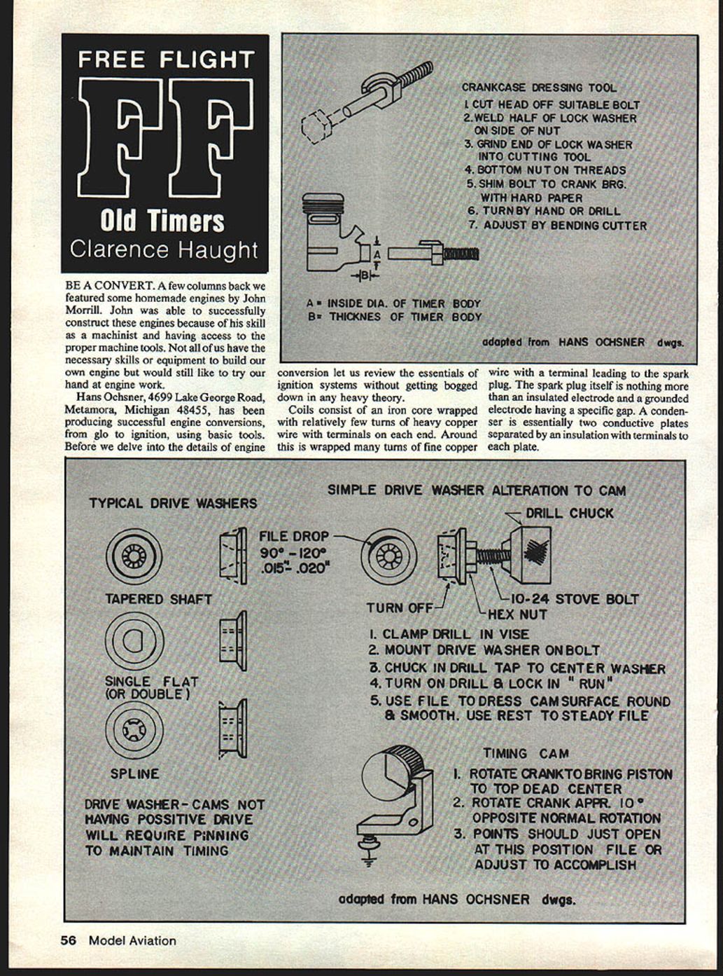
Choice is limited by your mechanical abilities, so you may need to compromise on size and bulk. The size of the selected point assembly will affect mounting in the limited space at the front of the crankcase, ahead of the intake port. That area will probably need truing up to provide a smooth, round surface for the timer assembly. Doing this in a lathe is best, but Hans suggests a simple tool made from a bolt and half of a lock washer (requires welding or brazing); local shops can usually perform the welding. Try for a finished diameter close to a standard drill size to simplify fabrication of the timer body.
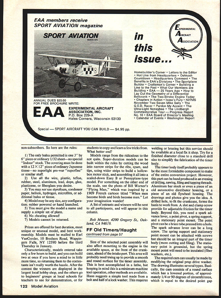
Mounting and the Timer Body
The timer body may seem the most formidable component, but it can be hand-produced in an evening of drilling, sawing, filing, and tapping threads. Materials that will serve include aluminum bar stock, a piece of an old automotive distributor housing, or part of an old flywheel housing.
Key features of the timer body:
- A drilled hole to fit the crankcase forms the basis.
- A slot and clamp screw provide adjustable friction fit.
- A spark advance lever, a point pivot, a spring support, and a stationary point mount are required.
- The point pivot can be a brass tube pressed into a hole with a brass pivot screw through the timer body.
- The spark advance lever can be a long screw.
- The spring support and stationary point mount can be attached with screws but are better if they are integral to the timer body (more cutting and filing).
- The stationary point is grounded; the movable point spring mount must be insulated (fiber washers, etc.).
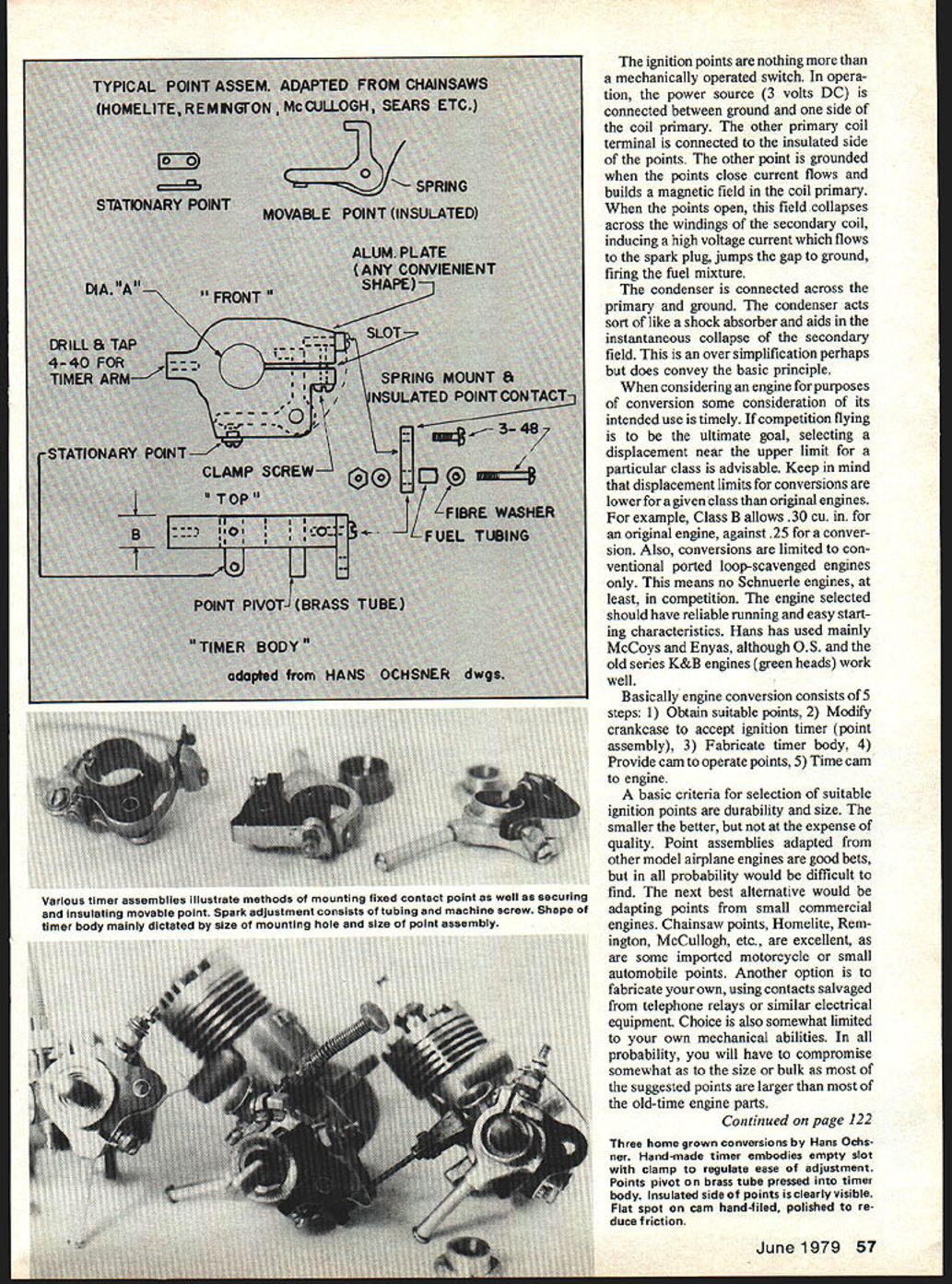
The Cam and Timing
The required cam can usually be made by modifying the original prop-drive washer. The cam should have a round surface with a lowered portion (a "low spot") occupying roughly 1/4 or 1/8 of the circumference; this lowered portion equals the desired point gap (about .015"–.018"). The low spot controls the duration that the points are closed (dwell), allowing a current build-up in the coil.
Some drive washers do not lend themselves to modification; in that case fabricate a suitable drive washer-cam.
Timing procedure:
- Install the timer assembly on the engine and position the timer to a desired "retarded" setting (this is primarily for convenience since the timer will be advanced during running by about 15° to 40° against crankshaft rotation).
- Rotate the crankshaft until the piston is at top dead center (TDC). Then rotate back (against normal rotation) about 10° — this is the position at which the points should crack open.
- Make suitable marks to guide you when cutting the cam drop.
- Ensure the cam can be reinstalled in the same position each time it is removed. If the engine has a drive washer-cam with a single flat there is no problem; if it has a double flat or splines, a suitable mark will suffice.
- If the engine has a tapered drive washer seat, it will need to be keyed to the shaft. The best method is to drill a hole parallel to the shaft with half the hole in the crankshaft and half in the cam, then install a crankpin.
With a little tinkering, the converted engine should be ready to run. Many converted glow engines can be a bit cantankerous to start; Hans suggests using an electric starter.
Final Notes
Converting an engine is not a simple task, but it is a rewarding challenge. The purpose of this discussion is not to undercut those who are in the engine conversion business—if anything, it supports the fact that they can earn their money.
Transcribed from original scans by AI. Minor OCR errors may remain.

