

FREE FLIGHT: OLD-TIMERS
By Bill Baker, 1902 Peter Pan, Norman, OK 73072
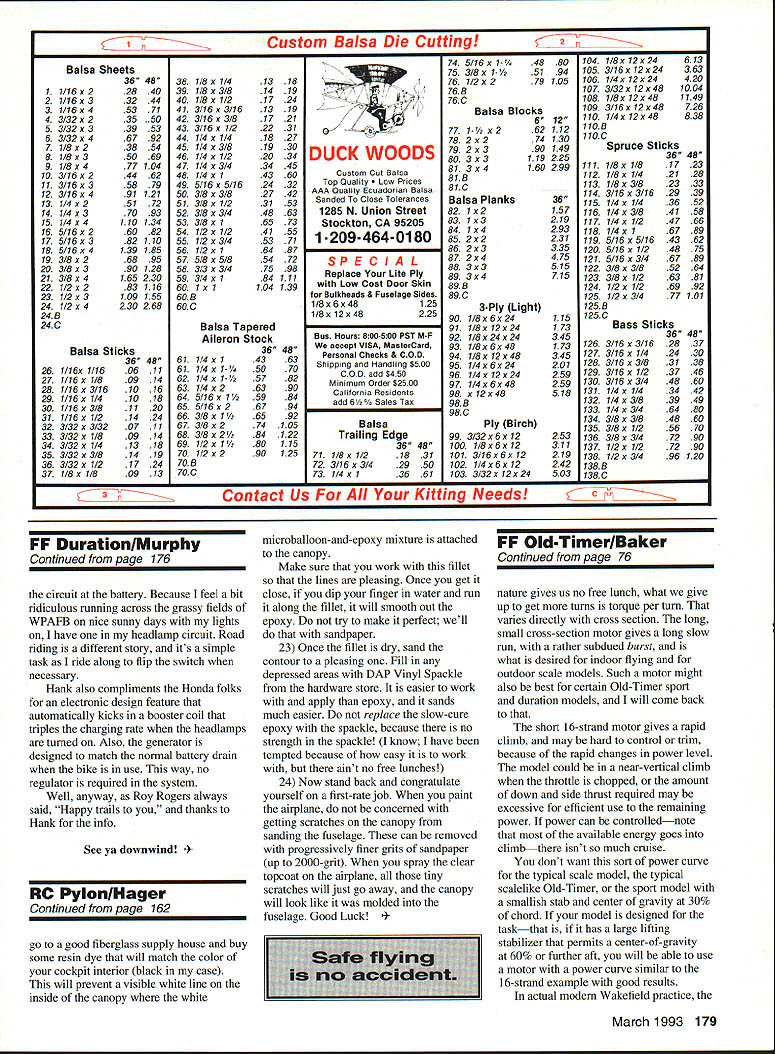
I think the fun of using rubber power is the choice of the numerous variables from which to tailor the power to the model, propeller, and desired flight performance. This month's column, with some introductory concepts, may be helpful to you who are not yet expert rubber fliers.
Torque, Power, and Energy
Torque is a twisting force, and for the purposes of this discussion, torque, power, and energy are treated as the same concept. Torque is easily measured, and if torque is plotted on a graph against turns, a curve results (see Figure 1).
The amount of torque at any given number of turns represents the power at that point. The area under the broken line in the graph represents the total energy available. It is apparent that it is necessary to approach the maximum turns for a motor to get full performance. Most of the energy comes in the last 20% of the turns, so that unwinding rubber has a short powerful burst followed by a rapid drop-off in power to a slowly diminishing level. The rapid change can cause serious trim problems, especially in certain types of models.
One factor that can contribute to a sharp "knee" in the power curve is the type or quality of the rubber. Good rubber (for our purpose) has a torque vs. turns curve that is a rather shallow concave curve; poor rubber will tend to have a J shape or a sharp angle between the cruise power and the initial burst power. If we know the power required for a particular model setup to climb, a horizontal line can be added to our graph; the energy above that line—that is, the area under the torque curve above the line—is the energy available for climb. The remaining energy below the horizontal line goes for a slow descent or cruise. For a given motor, lower airplane weight (or lowering that horizontal line) will shift more of the total energy into climb.
Motor Cross Section, Length, and Turns
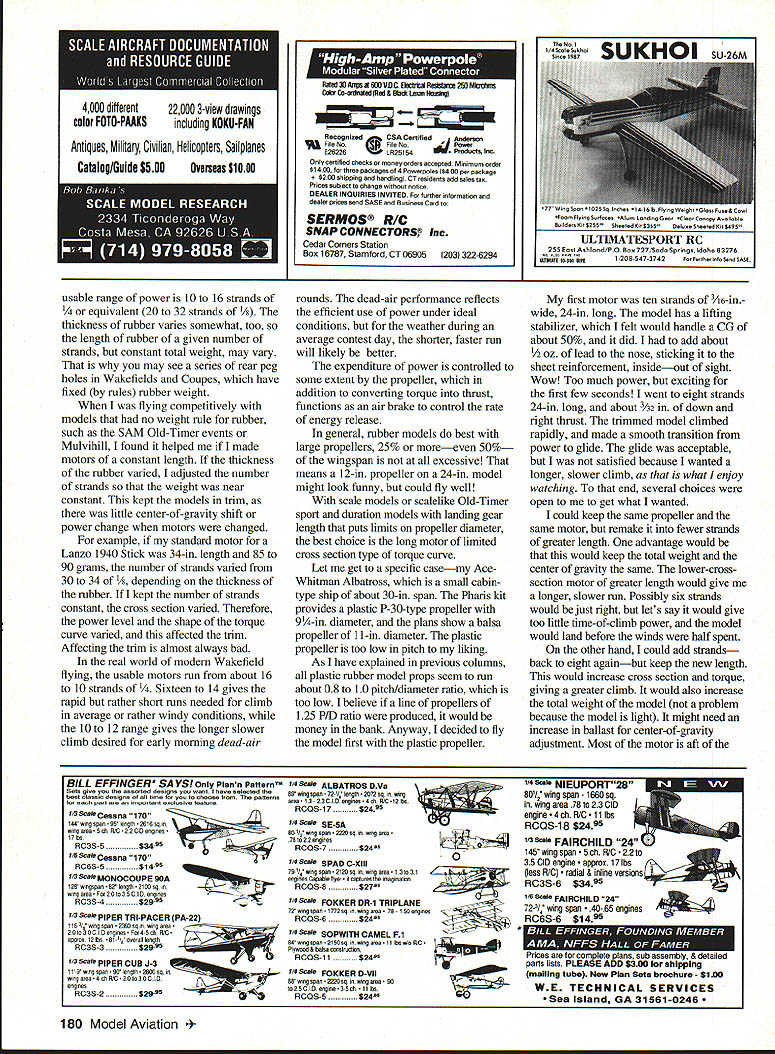
For convenience, let us use modern Wakefield practice to explain the next point, as it provides a fixed model weight/wing area/rubber situation: 40 grams of rubber.
Figure 2 shows approximate curves for this 40-gram motor arranged in 16, 8, and 4 strands of 1/4-in. strip. I have drawn a hypothetical line for climb power. The variable here is the cross section of the motor; since the weight remains constant, the length of the motor varies. Less cross section (that is, fewer strands) results in a longer motor. The number of turns possible also changes. Turns per unit of length varies inversely with cross section. That means the smaller the cross section, the more turns per inch. Nature gives us no free lunch: what we give up to get more turns is torque per turn. Torque varies directly with cross section.
The long, small–cross-section motor gives a long slow run with a rather subdued burst and is desired for indoor flying and for outdoor scale models. Such a motor might also be best for certain Old-Timer sport and duration models.
The short 16-strand motor gives a rapid climb and may be hard to control or trim because of the rapid changes in power level; the model could be in a near-vertical climb when the throttle is chopped, or the amount of power required may be excessive for efficient use of the remaining energy. If power can be controlled—note that most of the available energy goes into the climb—there isn't so much cruise.
You don't want this sort of power curve for the typical scale model, the typical scale-like Old-Timer, or the sport model with a smallish stab and center of gravity at 30% of chord. If your model is designed for the task—that is, if it has a large lifting stabilizer that permits a center of gravity at 60% or further aft—you will be able to use a motor with a power curve similar to the 16-strand example with good results.
In actual modern Wakefield practice, motor selection and airframe design are balanced to give a controllable climb and useful cruise rather than a single huge burst of power.
Practical Ranges and Considerations
Usable range of power is roughly 10 to 16 strands of 1/4-in. or equivalent (20 to 32 strands of 1/8-in.). The thickness of rubber varies somewhat, so the length of rubber of a given number of strands, but constant total weight, may vary. That is why you may see a series of rear peg holes in Wakefields and Coupes, which have fixed (by rules) rubber weight.
When I was flying competitively with models that had no rubber weight rule, such as SAM Old-Timer events or Mulvihill, I found it helped if I made motors of a constant length. If the thickness of the rubber varied, I adjusted the number of strands so that the weight was near constant. This kept the models in trim, as there was little center-of-gravity shift or power change when motors were changed.
For example, if my standard motor for a Lanzo 1940 Stick was 34 in. in length and 85 to 90 grams, the number of strands varied from 30 to 34 of 1/8 in., depending on the thickness of the rubber. If I kept the number of strands constant, the cross section varied. Therefore, the power level and the shape of the torque curve varied, and this affected the trim. Affecting the trim is almost always bad.
In the real world of modern Wakefield flying, the usable motors run from about 16 to 10 strands of 1/4 in. Sixteen to 14 strands give the rapid but rather short runs needed for climb in average or rather windy conditions, while the 10 to 12 range gives the longer slower climb desired for early morning dead-air rounds. The dead-air performance reflects the efficient use of power under ideal conditions, but for the weather during an average contest day, the shorter, faster run will likely be better.
The expenditure of power is controlled to some extent by the propeller, which in addition to converting torque into thrust, functions as an air brake to control the rate of energy release.
In general, rubber models do best with large propellers—25% or more of the wingspan; even 50% of the wingspan is not at all excessive. That means a 12-in. prop on a 24-in. model might look funny, but could fly well.
With scale models or scale-like Old-Timer sport and duration models with landing gear length that limits propeller diameter, the best choice is the long motor of limited cross section type of torque curve.
A Specific Case: Ace-Whitman Albatross
Let's get to a specific case—my Ace-Whitman Albatross, a small cabin-type ship of about 30-in. span. The Phoenix kit provides a plastic 1.80-type propeller with 9-1/2-in. diameter, and the plans show a balsa propeller of 11-in. diameter. The plastic propeller is too low in pitch to my liking.
As I have explained in previous columns, all plastic rubber-model props seem to run about 0.8 to 1.0 pitch/diameter (P/D) ratio, which is too low. I believe if a line of propellers with a 1.25 P/D ratio were produced, it would be money in the bank. Anyway, I decided to fly the model first with the plastic propeller.
My first motor was ten strands of 3/16-in.-wide rubber, 24 in. long. The model has a lifting stabilizer, which I felt would handle a center of gravity (CG) of about 50%, and it did. I had to add about 5/32 oz of lead to the nose, sticking it to the sheet reinforcement inside—out of sight. Wow! Too much power, but exciting for the first few seconds! I went to eight strands, 24 in. long, with about 3/32 in. down and right thrust. The trimmed model climbed rapidly and made a smooth transition from power to glide. The glide was acceptable, but I wanted a longer, slower climb, as that is what I enjoy watching. To that end, several choices were open to me to get what I wanted.
Choices to Alter Climb Performance
- Keep the same propeller and remake the motor into fewer strands of greater length.
- Advantage: total weight and CG remain essentially the same.
- Effect: lower cross section and greater length give a longer, slower run. Possibly six strands would be just right; but it might give too little time-of-climb power, and the model could land before the winds were half spent.
- Add strands (back to eight again) but keep the new length.
- Effect: increases cross section and torque, giving a greater climb. It also increases the total weight of the motor (not a problem here because the model is light) and might require additional ballast for CG adjustment. Most of the motor is aft of the hook, so small changes in length do not shift the CG much. An increase in rubber weight shifts the CG aft.
- Use the longer motor and braid it to avoid a CG shift between wound and unwound states.
- Note: braiding is not a big problem but should not be ignored.
Final Notes
The propeller choice and motor construction must be balanced for the conditions you expect: longer, lower–cross-section motors for calm conditions and scale-like flying; shorter, higher–cross-section motors for windier conditions and quicker climbs.
Questions welcome.
To be continued.
Transcribed from original scans by AI. Minor OCR errors may remain.

