
FREE FLIGHT OLD-TIMERS
Bill Baker, 1902 Peter Pan, Norman OK 73072
Introduction
This month's column is devoted to the changes I recommend when building the Korda 1939 Wakefield from the original Air Trails/Megow plan. Many of my suggestions will apply to almost any Old-Timer rubber model.
The Korda design is important not merely because it won the Wakefield contest in 1939, but because it was and is the most-built rubber design ever. It was simple, it was cheap, any kid could make one, and it flew!
For a detailed contemporary account of the 1939 Wakefield contest, get a copy of Frank Zaic's 1939 National Model Airplane Meet in Pictures — $7 plus $2.50 postage and handling from the Supply and Service Department at AMA (catalog number 3086). You might also like to review my column in the July 1988 issue of this magazine for my view of the results of that contest versus current Old-Timer contests.
Why change the original design?
A fair question might be, "why are any changes needed?" They fly fine just as Dick Korda designed them, and as Bill Winter drew the plans for Air Trails, but in 1939 a contest model was not expected to serve for many contests over a span of years. The use of the dethermalizer (DT) and the two- and three-minute max rules we now use are the major differences.
I flew the same Lanzo 1940 Stick for eight years and won two SAM (Society of Antique Modelers) championships and many other contests. Chet Lanzo told me he made "13 or 15" of the design in one season when he was competing with them. It really is a different game: one out-of-sight (OOS) flight won't win — it takes a string of shorter "max" flights.
Most of the changes I recommend involve dethermalizer modifications. They should be simple enough, but not if you build the model and then try to make the changes. Think and plan ahead.
Tail and stabilizer modifications
On the Korda, and many other rubber and gas designs, the stabilizer is shown glued to the upper longeron, and the longeron is not supported by an upright stick or sheet. If you add a typical rubber band sufficient to give reliable DT action at the leading edge, this unsupported length of longeron is likely to "give" a little, throwing off the trim, or even breaking.
My Lanzo Stick had a maddening habit of flying great until I got to a contest, and then it would stall in the glide. It cost me some wins until I realized that on contest days I put the rubber on tighter — the leading edge was pulled down harder on the unsupported longeron, and the resultant change in incidence caused the stall. A simple upright stick might do, but I prefer to fill the whole bay with 1/16" sheet with the grain vertical.
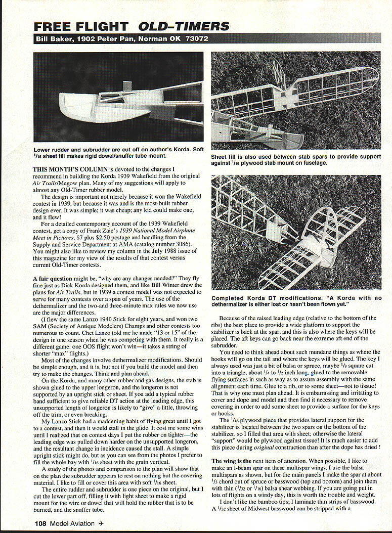
A study of the photos and comparison to the plan will show that on the plan the subrudder appears to rest on nothing but the covering material. I like to fill or cover this area with soft 1/16" sheet.
The original entire rudder and subrudder is one piece, but I cut the lower part off and fill it with light sheet to make a rigid mount for the wire or dowel that will hold the rubber that is to be burned, and for the snuffer tube.
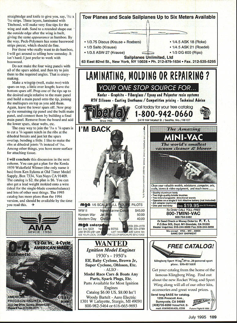
Because of the raised leading edge (relative to the bottom of the ribs), the best place to provide a wide platform to support the stabilizer is back at the spar, and this is also where the keys will be placed. The aft keys can go back near the extreme aft end of the subrudder.
Plan ahead where the tail hooks and keys will go. The key I always used was just a bit of balsa or spruce, maybe 1/8" square cut into a triangle, about 1/4" to 1/2" long, glued to the removable flying surfaces so assembly gives the same alignment each time. Glue to a rib or to some sheet — not to tissue. It is embarrassing and irritating to cover and dope a model and then find it necessary to remove the covering in order to add some sheet to provide a surface for the keys or hooks.
The 1/16" plywood piece that provides lateral support for the stabilizer is located between the two spars on the bottom of the stabilizer, so I fill that area with sheet; otherwise the lateral "support" would be plywood against tissue. It is much easier to add this piece during original construction than after the dope has dried.
Wing modifications and building sequence
The wing is the next item of attention. When possible, I like to make an I-beam spar on these multispar wings. I use the balsa multispars as shown on the plan, but for the main panels I make the spar about 1/3 chord out of spruce or basswood (top and bottom) and join them with thin (1/32" or 1/16") balsa shear webbing. If you are going to put lots of flights on a windy day, this is worth the trouble and the added weight.
I don't like the bamboo tips; I laminate thin strips of basswood. A 1/32" sheet of Midwest basswood can be stripped with a straightedge and knife to give, say, 1/32" x 1/32" strips. Three layers laminated with Titebond will make very fine tips for the wing and stab. Sand to a rounded shape out the outside edge after the wing is built, giving the same appearance as bamboo. Peck-Polymers also has some basswood strips precut, which should do fine.
For those who really want to use bamboo, I will get around to explaining how someday. It isn't hard; I just prefer to work with basswood.
Do not make the four wing panels with all of the spars added, and then try to join them to the required angles — that is crazy-making.
Suggested building sequence:
- Make a wingtip (well, make two) with the top spars a little over length; leave the bottom spars off.
- Prop one of the tips up to the desired angle relative to the main panel and build a main panel onto the tip, joining the multispar on top as you add them. Again, leave the lower spars off.
- Prop up the remaining tip panel and the built main panel, and connect them by building a final main panel.
- Remove from the board and add the lower spars, shear webs, etc.
The easy way to join the 1/16" x 1/8" spars is to cut a 1/8" square notch in the ribs at the dihedral breaks and just let the spars overlap, bending a little. I like to make the ribs at dihedral joints 1/8" instead of 1/16". Among other things, you have more surface for attaching tissue.
Conclusion and ordering plans
I will conclude this discussion in the next column.
You can get a plan for the Korda 1939 Wakefield Winner (the only name it has) from Ken Sykora at Old Timer Model Supply, Box 7334, Van Nuys CA 91409. The catalog is $2, the plan is $6. You can also get a lead weight molded onto a wire (ideal for the single-blade counterbalance) and lots of other neat things. The 1995 catalog has more plans than the 1994 version and should be available by the time you read this.
Transcribed from original scans by AI. Minor OCR errors may remain.

