
FREE FLIGHT OLD-TIMERS
Bill Baker
1902 Peter Pan, Norman OK 73072
This month I'd like to continue my discussion from the July issue on modifications to make the Korda Wakefield (or other models of the era) practical and long-lasting. Last month fuselage modifications for dethermalizers were covered.
Rear rubber-attachment point
Many designs (although not the Korda) could benefit from moving the rear rubber-attachment point forward. Some plans show this point somewhere below the stabilizer, even as far back as the trailing edge! If this is the case, move it forward a few bays (like the Korda). Less ballast will be needed to achieve a flyable center of gravity. This will also lower the total weight.
Replace the rubber-retaining dowel with an aluminum tube so a wire can be passed through it to hold the model securely for winding.
Winding tube and stooge
Even if you are like my old flying buddy George Perryman and never use a winding tube or mechanical stooge, this method is still helpful. Music wire (at least 1/8-inch) is passed through the rear peg, and the human stooge (read: victim) can hold the model more securely with less risk of damage.
Check to see if the nose block opening is wide enough to accept a winding tube. The Korda's is, but some (like Lanzo's 1940 Stick) need to be widened a bit to accept a one-inch winding tube.
An alternative to the hard-wall tube is the flexible plastic tube used to keep golf clubs separated. These tubes are larger than the one-inch thin-wall PVC pipe I use, but they will still squeeze in OK.
Fuselage reinforcement
Put a doubler inside the fuselage on the sheet fill so the balsa does not compress. This will keep the peg fit from getting sloppy. Thin plywood (3/32-inch), about the size of a nickel, will do. A one-inch-square piece of balsa installed cross-grain to the sheet fill will also work.
Wing mount
Moving forward the wing mount: add triangles or rectangles to the fuselage to provide mounts for the rubber-band dowels. None are shown on older plans, because the common practice was to loop the rubber strip over the top of the wing and under the lower longerons to hold the wing on. If you insist on doing it this way, you will break a lot of longerons, just like they did in the old days.
Anecdote
This reminds me of a story I heard about Cole Palen, the late WW I air show maestro. A very elderly former‑WWI Fokker pilot was brought by his great‑grandchildren to see Cole's show. The sights and sounds of the show brought nostalgic tears to the elderly gentleman's eyes. Cole asked him what they did about the groundlooping tendencies of the airplanes they flew in the old days. "Vell," the old gentleman said, "Ve had a lot of accidents."
Removable landing gear
You might also give some thought to making the landing gear removable. It simplifies storage and transportation. All this takes is modifying the landing gear "sandwich" so the wire can be slipped in and out. It can be held in with a piece of balsa sheet, spot-glued with Ambroid. Doped tissue can also be used.
This way, when you put 50 models (and one pair of socks) in your car for the SAM Champs, the landing gear won't poke holes in the wings. You might also have room for two pairs of socks!
Nose block construction and bearing
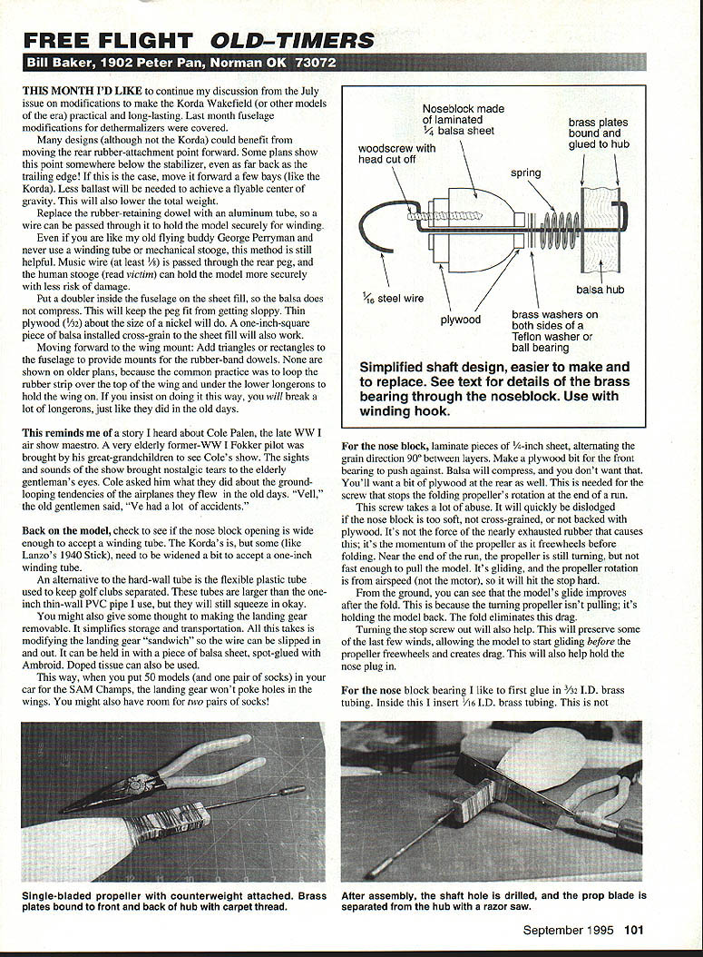
For the nose block, laminate pieces of 1/4-inch sheet, alternating the grain direction 90° between layers. Make a plywood bit for the front bearing to push against. Balsa will compress, and you don't want that. You'll want a bit of plywood at the rear as well. This is needed for the screw that stops the folding propeller's rotation at the end of a run.
This screw takes a lot of abuse. It will quickly be dislodged if the nose block is too soft, not cross-grained, or not backed with plywood. It's not the force of the nearly exhausted rubber that causes this; it's the momentum of the propeller as it freewheels before folding. Near the end of the run, the propeller is still turning, but not fast enough to pull the model. It's gliding, and the propeller rotation is from airspeed (not the motor), so it will hit the stop hard.
From the ground, you can see that the model's glide improves after the fold. This is because the turning propeller isn't pulling; it's holding the model back. The fold eliminates drag.
Turning the stop screw out will also help. This will preserve some of the last few winds, allowing the model to start gliding before the propeller freewheels and creates drag. This will also help hold the nose plug in.
For the nose block bearing I like to first glue in 3/32-inch I.D. brass tubing. Inside this I insert 1/16-inch I.D. brass tubing. This is not glued in; it's oiled to turn freely.
The 1/16-inch steel propeller shaft turns in the middle tube; the middle tube turns freely in the outer housing. If the shaft distorts during the run and binds on the middle tube, it's unlikely that the middle tube will distort enough to bind on the outer tube.
High-tech, modern Wakefields use ball bearings in the nose block. These are used to take the lateral loads of the shaft more than they are used for the load of the motor against the nose block.
I do not recommend gluing bits of brass to the front and back of the nose block as the bearing. This method is shown on many plans — it obviously works, but I don't trust its reliability.
I used the last Korda Wakefield I made for about ten years before I sold it. I doubt Korda kept one that long.
Propellers and hubs
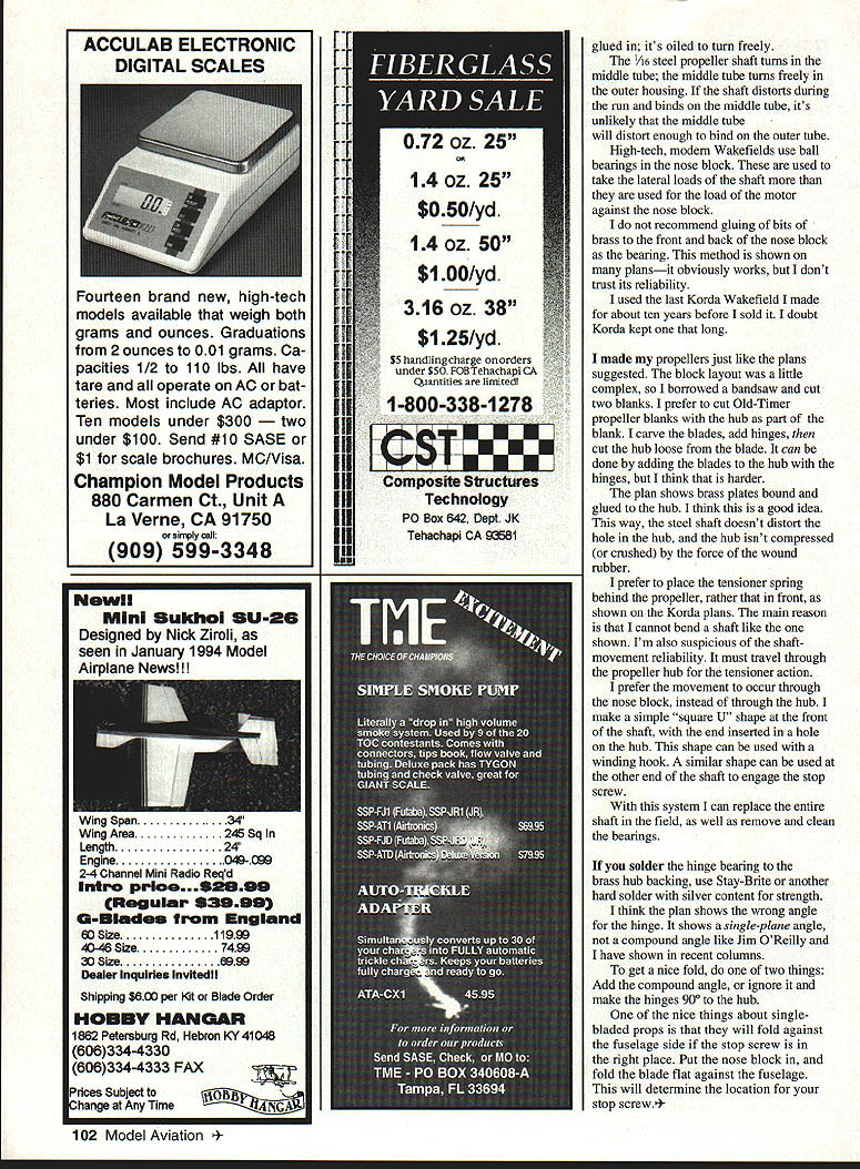
I made my propellers just like the plans suggested. The block layout was a little complex, so I borrowed a bandsaw and cut two blanks. I prefer to cut Old-Timer propeller blanks with the hub as part of the blank. I carve the blades, add hinges, then cut the hub loose from the blade. It can be done by adding the blades to the hub with the hinges, but I think that is harder.
The plan shows brass plates bound and glued to the hub. I think this is a good idea. This way, the steel shaft doesn't distort the hole in the hub, and the hub isn't compressed (or crushed) by the force of the wound rubber.
If you solder the hinge bearing to the brass hub backing, use Stay-Brite or another hard solder with silver content for strength.
Tensioner, shaft, and field serviceability
I prefer to place the tensioner spring behind the propeller, rather than in front, as shown on the Korda plans. The main reason is that I cannot bend a shaft like the one shown. I'm also suspicious of the shaft-movement reliability. It must travel through the propeller hub for the tensioner action.
I prefer the movement to occur through the nose block, instead of through the hub. I make a simple "square U" shape at the front of the shaft, with the end inserted in a hole in the hub. This shape can be used with a winding hook. A similar shape can be used at the other end of the shaft to engage the stop screw.
With this system I can replace the entire shaft in the field, as well as remove and clean the bearings.
Hinge angle and folding
I think the plan shows the wrong angle for the hinge. It shows a single-plane angle, not a compound angle like Jim O'Reilly and I have shown in other articles.
To get a nice fold, do one of two things:
- Add the compound angle, or
- Ignore it and make the hinges 90° to the hub.
One of the nice things about single-bladed props is that they will fold against the fuselage side if the stop screw is in the right place. Put the nose block in, and fold the blade flat against the fuselage. This will determine the location for your stop screw.
Transcribed from original scans by AI. Minor OCR errors may remain.

