
Free Flight
Scale/Sport
Ralph D. Kuenz
HAVE TO START this out with a first things first format, so here it is. Errata—three items from my last article need to be corrected: 1) the unusual Vought V-173 pictured was built by former Vought engineer Dick Johnson, 2) Pres Bruning's W‑I‑G‑H‑T quadraplane got its name significantly changed, 3) the average weight rubber scale ship weighs 1/2 oz per ft.
The airplane looks great except for the "wow" in the fuselage. It's moon‑shaped and leans a little to the left—comments you've all heard when the fuselage is not too well aligned.
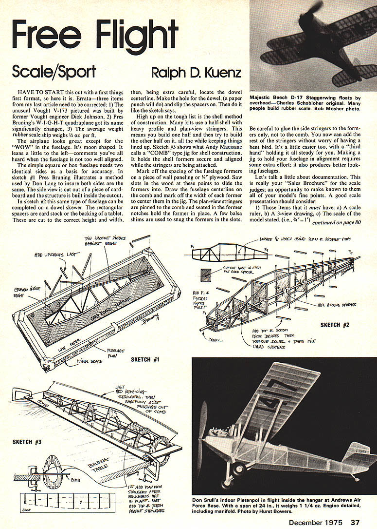
The simple square or box fuselage needs two identical sides as a basis for accuracy. In sketch #1 Pres Bruning illustrates a method used by Don Lang to insure both sides are the same. The side view is cut out of a piece of cardboard and the structure is built inside the cutout. In sketch #2 this same type of fuselage can be completed on a dowel skewer. The rectangular spacers are card stock or the backing of a tablet. These are cut to the correct height and width, then, being extra careful, locate the dowel centerline. Make the hole for the dowel (a paper punch will do) and slip the spacers on. Then do like the sketch says.
High up on the tough list is the shell method of construction. Many kits use a half‑shell with heavy profile and plan‑view stringers. This means you build one half and then try to build the other half on it, all the while keeping things lined up. Sketch #3 shows what Andy Macisaac calls a "COMB" type jig for shell construction. It holds the shell formers secure and aligned while the stringers are being attached.
Mark off the spacing of the fuselage formers on a piece of wall paneling or 1/4" plywood. Saw slots in the wood at these points to slide the formers into. Draw the fuselage centerline on the comb and mark off the width of each former to center them in the jig. The plan‑view stringers are pinned to the comb and seated in the former notches to hold the former in place. A few balsa shims are used to snug the formers in the slots.
The comb now can be used to add the rest of the stringers. Don't worry about having a bent bird; it's a little easier to add the rest with a "third hand" holding it steady. Making a jig to hold fuselage alignment requires some extra effort; it also produces better looking fuselages.
Let's talk a little about documentation. This is really your "Sales Brochure" for the scale judges; an opportunity to make known to them all of your model's fine points. A good scale presentation should consider:
1) Those items that it must have:
- a) A scale ruler,
- b) A 3‑view drawing,
- c) The scale of the model stated (i.e., 3/4" = 1').
2) Items that should have:
- a) Photo of the real aircraft,
- b) Proof of color markings (color photo possible),
- c) A brief written description of the prototype/model.
3) An easy‑to‑follow format. So take some time to build the model presentation. Go to Kresge's or any office supply store and buy a simple folder to contain scale data; put together:
Page One—brief written description of the prototype (two paragraphs will do): e.g., model depicts Westland Lysander, British Army cooperation aircraft, WWII, etc.
Page Two—clearly line state scale of model. Now, following the AMA Rule Book, lead judges through a ritual simple description of the model's features applicable. Make a scale ruler strip of heavy paper. Mark off one edge in feet scale—3‑view drawing probably has a scale bar. Mark off the other edge in feet scale—the model ruler should be long enough to measure centerline to wingtip. Include bulky scale reference material such as precious old magazine type articles in a folder pocket inside the cover; remember to tell judges the page the magazine reference is on. Thus equipped, judges with a wary, weary eye should look a little more favorably on the scale model.
Tips/Techniques: Here's a couple ways to help Japanese tissue trimming. Remember: use dark color trim over lighter background; when cutting out trim, don't... try to do your cutting from a full sheet of tissue. Cut it into 8 x 10 pieces to work with. These can be sandwiched in the last two pages of a notebook‑size tablet. Draw your trim, numbers, stripes, letters, etc. on the tablet paper and, using a brand‑new #11 X‑Acto blade, cut right through the tablet paper sandwich. The cardboard backing on the tablet helps keep the blade point from dulling. Use the cheapest tablet you can buy. The yellow rough paper grips the tissue and keeps it from sliding.
Another method, used by Andy MacIsaac, is to draw your trim on a sheet of plain paper. Then using thinned clear dope, cement several layers of Japanese tissue to the back side. Let dry, and cut out your trim. (Same as above — layers can then be "tickled" off this stack one at a time with thinner and applied to the model.) The stack is stiffer and easier to handle than individual tissue pieces.
Got the word from Braniff Airlines pilot Vic Larsen (3rd FF Scale '75 NATS) that the Texas Aeromasters are looking for Scale/Sport types. Contact: Aeromasters, Route 3, Roanoke, Texas, 76262.
Here are some sources for scale data: Caproni — Avia Caproni, Caproni Rivetta, Vizzola Ticino, Italy; Beech Aircraft Corp., Wichita, Kansas 67201; DeHavilland Aircraft of Canada Ltd., Downsview, Ontario, Canada.
Transcribed from original scans by AI. Minor OCR errors may remain.

