
FREE FLIGHT SPORT and SCALE
Author
Fernando Ramos 19361 Mesa Dr., Villa Park, CA 92861
PENDULUM CONTROL for Free Flight (FF) Scale Models
There are a couple of reasons why you don't see many Scale models equipped with pendulums for stability in flight. For one, many modelers don't know what a pendulum is or does in a model airplane. Those who do know often aren't willing to put in the time required to install one. It isn't that much of a hassle, but extra work is too much for some.
I want my Scale models to have the best opportunity for successful flight without the dreaded spiral doing them in. I hope many of you give it a try and find how gratifying it is to see a Scale model under the control of a pendulum.
Why a pendulum on the ailerons?
- The easiest flying surface to control with a pendulum is the rudder, but yaw is not what gets Scale models into trouble—spiral instability is.
- Therefore I recommend hooking the pendulum to the ailerons. With the pendulum on the ailerons, the flight pattern is typically a safe banking turn: the model banks, the pendulum reacts and the model straightens out, then returns to a safe bank, etc. It is spectacular to see.
Many modelers who are familiar with pendulums think of the hanging pendulums that swing back and forth (like a grandfather clock) hooked to the rudder. I have seen those work, but in a tight turn under power the mass of the pendulum is affected by centrifugal force, which can create an even tighter turn and cause a crash. A pendulum that influences the ailerons is affected less by centrifugal force and lets gravity predominate in a bank.
Pendulum construction and installation
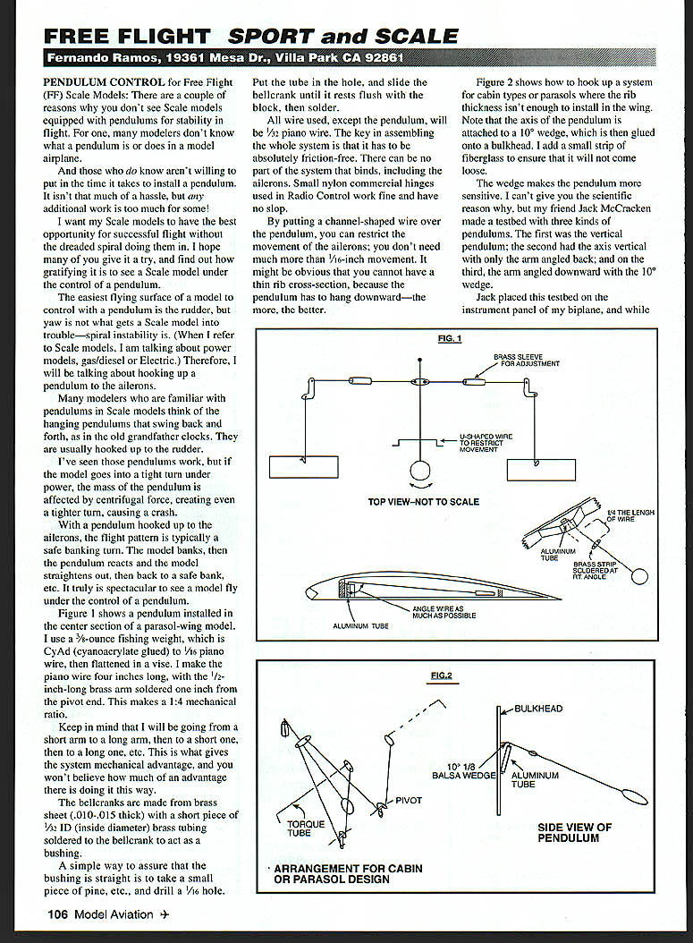
Figure 1 shows a pendulum installed in the center section of a parasol-wing model. Construction details I use:
- Pendulum weight: 3/8-ounce fishing weight, Cy-A (cyanoacrylate) glued to 1/16" piano wire, then flattened in a vise.
- Pendulum wire length: 4" piano wire total, with a 1/2" long brass arm soldered 1" from the pivot end — yielding a 1:4 mechanical ratio.
- The system alternates from short arm to long arm to short arm, etc., giving mechanical advantage. The advantage is surprisingly large when done this way.
Bellcranks and bushings:
- Bellcranks: made from brass sheet .010–.015" thick.
- Bushing: short piece of 1/32" ID brass tubing soldered to the bellcrank.
- To ensure the bushing is straight:
- Drill a 1/16" hole in a small block of pine.
- Put the tube in the hole and slide the bellcrank until it rests flush with the block.
- Solder the tube in place.
Wire and friction:
- All control wire except the pendulum itself should be 1/32" piano wire.
- The key to the whole system is that it must be absolutely friction-free. There can be no part that binds, including the ailerons.
- Small nylon commercial hinges (used in R/C work) work well and have no slop.
Aileron movement and rib thickness:
- By placing a channel-shaped wire over the pendulum you can restrict aileron movement; you don't need much — about 1/16" movement is sufficient.
- The pendulum must hang downward, so the wing/rib cross-section must be thick enough to accommodate the pendulum shaft. Thin ribs may not work.
Mounting variations and sensitivity (Figures 2 and 3)
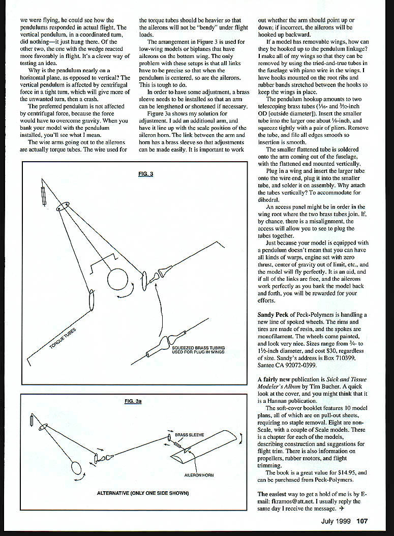
Figure 2 shows how to hook up a pendulum for cabin types or parasols where the rib thickness isn't enough to install the pendulum in the wing. Key points:
- The pendulum axis is attached to a 10° wedge, which is glued onto a bulkhead and reinforced with a small strip of fiberglass.
- The 10° wedge makes the pendulum more sensitive. (Empirical tests by Jack McCracken confirmed this.)
- Jack's testbed had three pendulum types: (1) a vertical pendulum, (2) axis vertical with arm angled back, and (3) axis with arm angled downward on a 10° wedge.
- In coordinated turns the vertical pendulum simply hung and did not respond favorably; the other two configurations reacted well. A pendulum nearly in the horizontal plane is less affected by centrifugal force than a vertical pendulum, so gravity predominates and gives better correction in banks.
Torque tubes and low‑wing/bottom‑aileron biplane setups (Figure 3):
- The wire arms going out to the ailerons are actually torque tubes. Use heavier torque-tube wire if the ailerons will be "bendy" under flight loads.
- The arrangement in Figure 3 is used for low-wing models. Biplanes with ailerons on the bottom wing present a challenge: all links must be precise so the ailerons are centered when the pendulum is centered.
- To allow adjustment, install a brass sleeve so the arm can be lengthened or shortened.
Figure 3a — adjustment solution:
- Add an additional arm to line up with the scale-position aileron horn.
- The link between the arm and the horn uses a brass sleeve for easy adjustment.
- Important: decide whether the arm should point up or down; if incorrect, the ailerons will be hooked up backward.
Removable wings and tube connections
If the model has removable wings, use small mating tubes so wings can be removed with piano‑wire stubs in the wings and tubes in the fuselage. I use hooks on the root ribs and rubber bands between the hooks to keep the wings in place.
Pendulum hookup method (telescoping tubes):
- Use two brass tubes: 1/16" and 3/32" OD.
- Insert the smaller tube into the larger about 1/8" and squeeze tightly with pliers; remove and file all edges smooth for smooth insertion.
- The smaller flattened tube is soldered to the arm coming out of the fuselage with the flattened end mounted vertically.
- Plug in a wing, insert the larger tube onto the wire end in the wing, plug it into the smaller tube, and solder in place on final assembly.
- Attach the tubes vertically to accommodate dihedral.
- Consider an access panel in the wing root where the tubes join so you can realign the tubes if needed.
Important notes and limitations
- Equipping a model with a pendulum does not fix major configuration problems: warps, engine set with zero thrust, center of gravity out of limits, etc., will still prevent good flight. The pendulum is an aid; when all links are free and ailerons work correctly, you will be rewarded for your effort.
Products and publications
- Spoked wheels from Peck‑Polymers (Sandy Peck): rims and tires are resin, spokes are monofilament, wheels come painted.
- Sizes: 3/4" to 1-1/2" diameter.
- Price: $30 each (regardless of size).
- Address: Box 710399, Santee, CA 92072-0399.
- Stick and Tissue Modeler's Album by Tim Bucher:
- Soft-cover booklet with 10 model plans on pull-out sheets (no staple removal). Eight are non-scale, with a couple of Scale models.
- Each model has a chapter describing construction and flight-trim suggestions. Includes information on propellers, rubber motors, and flight trimming.
- Price: $14.95, available from Peck‑Polymers.
Contact
The easiest way to reach me is by e-mail: kframos@att.net. I usually reply the same day.
Transcribed from original scans by AI. Minor OCR errors may remain.

