
FREE FLIGHT: Sport and Scale
Fernando Ramos 19361 Mesa Dr., Villa Park CA 92861
At last year's FAC (Flying Aces Club) Nats, I made an observation while watching many beautifully crafted Scale models fly overhead: although almost every rubber-powered model was flying as if it were on rails, many were flying much faster than they should have been.
Was this attributable to too much power, or to the prop pulling the model through the sky? Most FACers build on the light side rather than too heavy, so it couldn't be that these models were overpowered. Most of the models I saw flying too fast were propelled by plastic props.
I am not here to badmouth plastic props. The obvious reasons for using them are that you save time not having to carve one, and they do not break very easily. But generally speaking, most plastic props do not have enough pitch; therefore they spin faster than necessary.
Most of you have probably seen pure indoor models that are covered with film for lightness. Even the props they use are built up and covered with film. When these props make one revolution, the model moves forward a substantial amount. These delicate models can stay up nearly an hour at a time! Wouldn't it be nice to be able to get Scale models flying longer than they do most of the time, without the aid of a thermal?
Most of the top competitors at an FAC Nats use a carved prop, or one that is the "cottage cheese" variety where blade area and pitch can be altered fairly easily. The essence of this article is from Fulton Hungerford. He was very astute at almost every phase of modeling, and at one time was always in the winner's box with some unusual Scale model. I put forth this article on props so that you can consider the parameters involved for your next project.
Most of you have read articles dealing with propellers, but how many of you have actually put the information into practice? Competitive free flighters who fly Wakefield and Mulvihill models know a great deal about propellers. How about the average rubber Scale modeler?
Too often it is so much easier to use the plastic prop that comes with a kit than it is to carve or laminate one for the model you have just completed. Yet in order to be competitive, the propeller is one of the most important considerations.
Propeller size, pitch and calculations
Where does one start? What size block should be used? What size block gives what pitch?
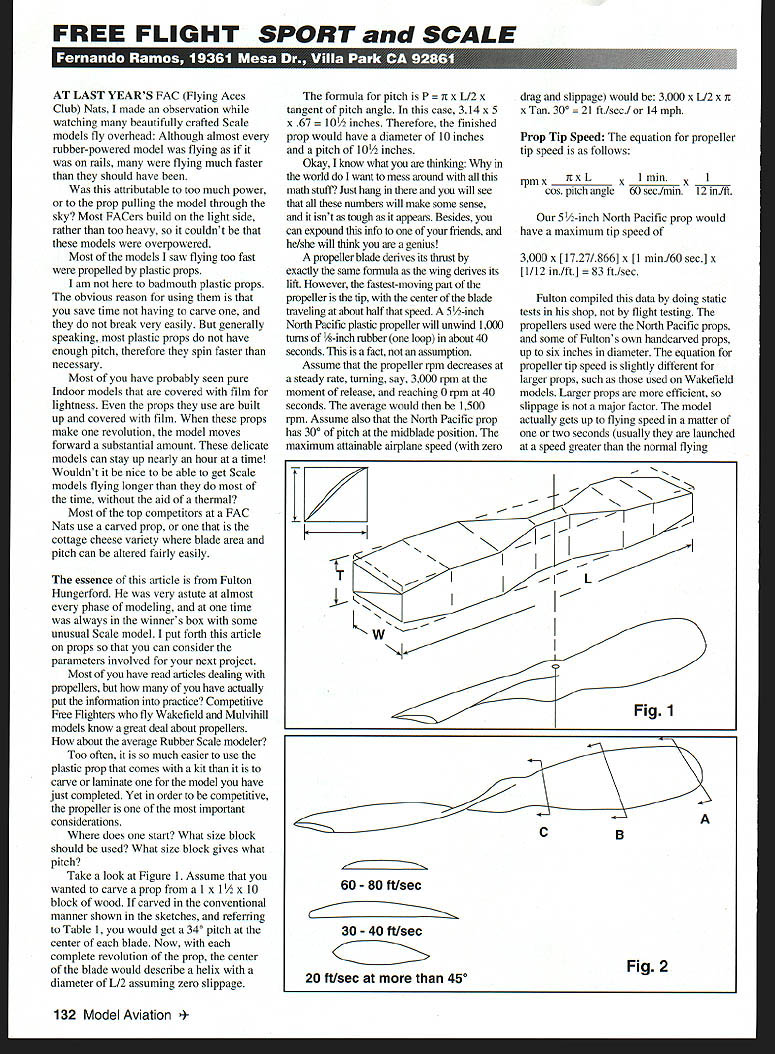
Take a look at Figure 1. Assume that you wanted to carve a prop from a 1 x 1-1/2 x 10 block of wood. If carved in the conventional manner shown in the sketches, and referring to Table I, you would get a 34° pitch at the center of each blade. Now, with each complete revolution of the prop, the center of the blade would describe a helix with a diameter of L/2 assuming zero slippage.
The formula for pitch is: P = π × (L/2) × tan(pitch angle).
In this case, 3.14 × 5 × 0.67 = 10-1/2 inches. Therefore, the finished prop would have a diameter of 10 inches and a pitch of 10-1/2 inches.
Okay, I know what you are thinking: why in the world do I want to mess around with all this math stuff? Just hang in there and you will see that all these numbers will make some sense, and it isn't as tough as it appears. Besides, you can expound this info to one of your friends, and he or she will think you are a genius!
A propeller blade derives its thrust by exactly the same principles as a wing derives its lift. However, the fastest-moving part of the propeller is the tip, with the center of the blade traveling at about half that speed. A 5-1/2-inch North Pacific plastic propeller will unwind 1,000 turns of 1/8-inch rubber (one loop) in about 40 seconds. This is a fact, not an assumption.
Assume that the propeller rpm decreases at a steady rate, turning, say, 3,000 rpm at the moment of release and reaching 0 rpm at 40 seconds. The average would then be 1,500 rpm. Assume also that the North Pacific prop has 30° of pitch at the midblade position. The maximum attainable airplane speed (with zero drag and slippage) would be:
3,000 × [pitch factor] × (1 min / 60 sec) × (1/12 in / ft) = 83 ft/sec
Fulton compiled this data by doing static tests in his shop, not by flight testing. The propellers used were the North Pacific props, and some of Fulton's own hand-carved props up to six inches diameter. The equation for propeller tip speed is slightly different for larger props, such as those used on Wakefield models. Larger props are more efficient, so slippage is not a major factor. The model actually gets up to flying speed in a matter of one or two seconds (usually they are launched at a speed greater than the normal flying speed).
During its powered flight a Wakefield is very close to its flying speed, so it is a good assumption to take average rpm to get flying speed. A Wakefield prop 24 inches diameter and 24 inches pitch unwinds approximately 400 turns in about 40 seconds; this translates to an average of 600 rpm (10 rps). The model flying speed would be:
10 rps × 24-inch pitch = 240 in/sec = 20 ft/sec.
The equation for propeller tip speed for large props follows: rpm × Dia × π / 60 sec/min × 1/12 in/ft.
In this case the average tip speed would be about 65.9 ft/sec. Of course, higher torque from a fully wound rubber motor would yield greater tip speed immediately after launch, but I doubt it would double the average. Maximum tip speed is probably 80–90 ft/sec.
Propeller Blade Airfoils
From the above calculations and observations, it appears that rubber-powered models travel at nearly 20 ft/sec with propeller tip speeds on the order of 60 to 80 ft/sec. To be effective at those speeds, the tips should not be very heavily undercambered; the middle of the blade can be undercambered somewhat toward the trailing edge, but near the hub the prop does not need undercamber at all (see Fig. 2).
It appears that the area close to the hub is very inefficient and is required for strength only. In the case of folding props, where this area is reinforced with metal, wire, etc., the best shape appears to be a sharp-edged symmetrical airfoil, so that it does not create any drag.
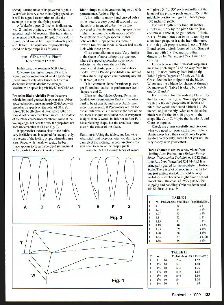
Blade shape must have something to do with the performance. Refer to Fig. 3 for profiles A through G described below.
- A: Similar to many hand-carved balsa props — a very good all-around prop shape.
- B: Intended to be like piston-powered full-scale airplane props. Tip speeds for these are higher than possible with rubber power; they are very efficient at high speeds. Fulton believes that slippage causes them to unwind too fast on rubber models. He never had much luck with these props.
- C: A contradiction in uses. Very similar to the shape of most turboprop propellers, where the speed approaches supersonic velocity, yet also similar to commercial plastic props for small rubber models. North Pacific blades are similar to this shape. Tip speeds are probably around 80 ft/sec at most.
- D: A common shape for rubber power, but Fulton reported better performance from shapes A and C.
- E: Similar blade used by George Perryman (a well-known competitive rubber flier who has won a great deal). If Perryman's reason for this blade is to increase the area at the tip, then F should be studied too.
- F: A wide-tip blade intended to increase area at the tip — worth studying for performance effects.
- G: Has a pleasing shape, but the area tends to list more toward the center of the blade and would be inferior to E or F if increased tip area is desired.
Summary: Using the tables, and knowing what pitch and prop diameter you desire, you can select the rectangular cross-section area you need to achieve the proper pitch.
Example: A 1 × 1-1/2-inch block of wood will give approximately a 3/4-inch or 34° pitch at the blade midpoint, regardless of the length of the prop. A pitch angle of 34° at the midblade position will give a 10-inch prop about 10-1/2 inches of pitch.
For any length other than 10 inches, multiply by the pitch factor (last column in Table II) to get inches of pitch.
A 1 × 1-1/2-inch block of balsa is too big for a six-inch prop. If a six-inch prop is wanted, go to Table II and select a pitch factor of 1.00. Since it lines up with 1 × 1-1/2, multiply that dimension by 1/10 and get 5/8 × 1/10 inch for carving.
Fulton preferred that full-scale airplanes measure pitch angle 3/4 of the way from hub to tip. He used halfway from hub to tip. Table I gives degrees of pitch vs. block cross-section for the midpoint of the blade. When carving a blade for shapes A through D, and even G, Table I is adequate; but watch out for E and F.
For instance, for any wide-tip blade, lay the blank out like Fig. 4. Suppose you wanted a 10-inch prop with 10 inches of pitch. You would then need a block 1 × 3-1/4 inches — exactly twice as wide as the block used for the 10 × 10 prop with a shape like A or C. Maybe that is why A and C are so popular.
Check the charts carefully and pick out what you need for your next project. Use a plastic prop first, then switch over to your hand-carved beauty, and I'll bet you will be very happy with your effort.
Had a chance to review a new video from Harding Aero Productions: Rubber Power Scale, Construction Techniques (4782 Unity Line Rd., New Waterford OH 44445). It is principally geared for the neophyte in rubber Scale. There is a lot of good information for one just getting started. It would be very useful for a teacher who might have a school model club. The cost is $19.95 plus $3 for shipping and handling. Ohio residents need to add $1.20 sales tax.
Transcribed from original scans by AI. Minor OCR errors may remain.

