
FREE FLIGHT SPORT and SCALE
Bill Warner, 1370 Monache Avenue, Porterville, CA 93257
GEARS AND GEARLESS DRIVES for Rubber Power
Most fancy transmissions composed of multiple motors driving one prop through gears or crank arrangements, or one motor driving multiple props through similar devices, have one common trait—most modelers don't use them.
They can increase a model's performance up to 25%. However, unless they are light, mechanically reliable, relatively friction-free, well-balanced, and are used with the proper motor/prop combination, they can and do reduce performance significantly compared with simple direct drive.
There are many great reasons for employing odd power transfers:
- the size and placement of prop(s)
- leveling the power curve
- reducing vibration caused by long, whipping motors
- compensating for the lack of room for a long motor (as in a nacelle)
- preventing stalls caused by unwound motors that shift the CG rearward
There have been a number of notable geared model successes in competition around the world in recent years. The prestigious Flying Aces Club has even gone so far as to ban them from competition for being unfair. (How's that for a recommendation?)
Much has been written about gears, and I do not intend to go deeply into them here. For a lengthy discussion on that topic (complete with the obligatory math for your engineer types), get Bill McCombs' book: Flying and Improving Scale Models. Send $14.95 postage paid to A/C Data, P.O. Box 763576, Dallas, TX 75224. Not much, however, has been written on what Bob Thompson calls "hovespian" or synchronized cranking devices.
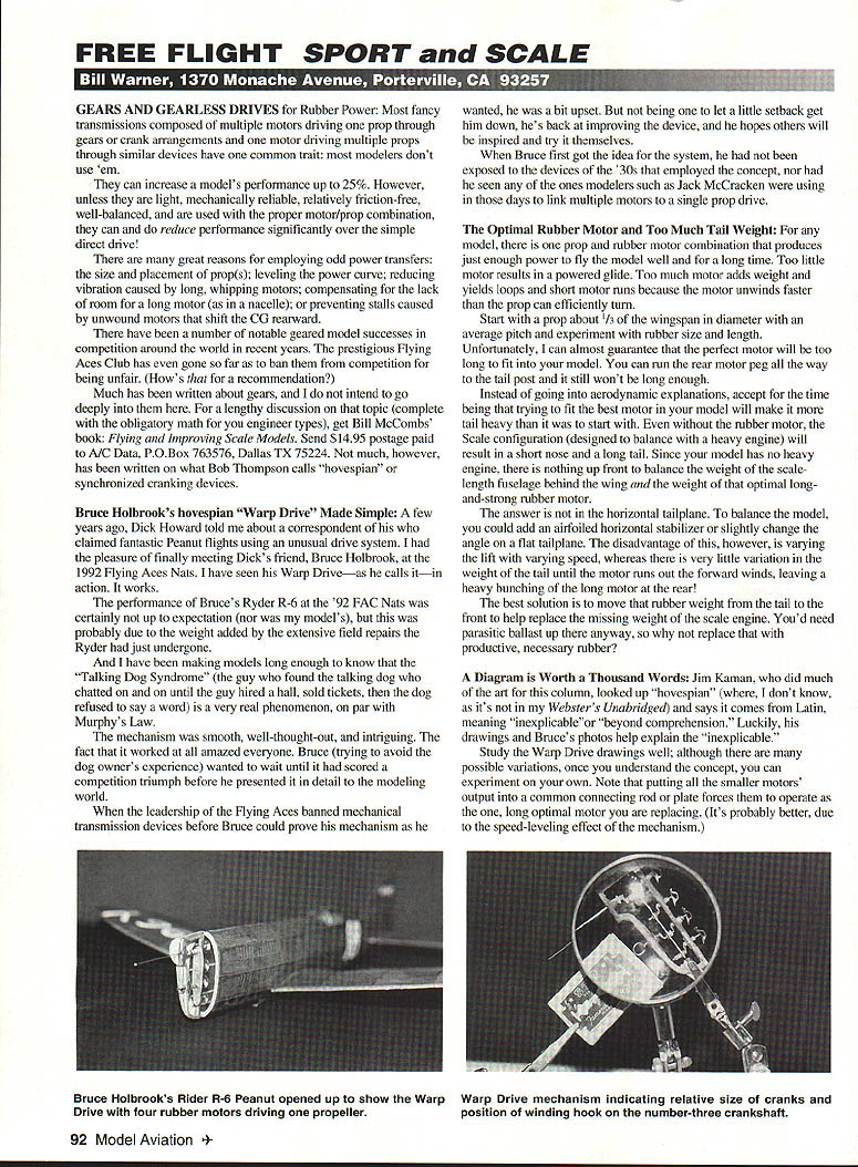
Bruce Holbrook's hovespian "Warp Drive" Made Simple
A few years ago, Dick Howard told me about a correspondent of his who claimed fantastic Peanut flights using an unusual drive system. I had the pleasure of finally meeting Dick's friend, Bruce Holbrook, at the 1992 Flying Aces Nats. I have seen his Warp Drive—as he calls it—in action. It works.
The performance of Bruce's Ryder R-6 at the '92 FAC Nats was certainly not up to expectation (nor was my model's), but this was probably due to the weight added by the extensive field repairs the Ryder had just undergone.
And I have been making models long enough to know that the "Talking Dog Syndrome" (the guy who found the talking dog who chatted on and on until the guy hired a hall, sold tickets, then the dog refused to say a word) is a very real phenomenon, on par with Murphy's Law.
The mechanism was smooth, well-thought-out, and intriguing. The fact that it worked at all amazed everyone. Bruce (trying to avoid the dog owner's experience) wanted to wait until it had scored a competition triumph before he presented it in detail to the modeling world.
When the leadership of the Flying Aces banned mechanical transmission devices before Bruce could prove his mechanism as he wanted, he was a bit upset. But not being one to let a little setback get him down, he's back at improving the device, and he hopes others will be inspired and try it themselves.
When Bruce first got the idea for the system, he had not been exposed to the devices of the '30s that employed the concept, nor had he seen any of the ones modelers such as Jack McCracken were using in those days to link multiple motors to a single prop drive.
The Optimal Rubber Motor and Too Much Tail Weight
For any model, there is one prop and rubber motor combination that produces just enough power to fly the model well and for a long time. Too little motor results in a powered glide. Too much motor adds weight and yields loops and short motor runs because the motor unwinds faster than the prop can efficiently turn.
Start with a prop about one-third of the wingspan in diameter with an average pitch and experiment with rubber size and length.
Unfortunately, I can almost guarantee that the perfect motor will be too long to fit into your model. You can run the rear motor peg all the way to the tail post and it still won't be long enough.
Instead of going into aerodynamic explanations, accept for the time being that trying to fit the best motor in your model will make the tail heavy. Even without the rubber motor, the scale configuration is designed to balance the weight of the scale-length fuselage behind the wing and the weight of that optimal long-and-strong rubber motor. The answer is not in the horizontal tailplane. To balance the model, you could add an airfoiled horizontal stabilizer or slightly change the angle on a flat tailplane. The disadvantage of this, however, is varying the lift with varying speed, whereas there is very little variation in the weight of the tail until the motor runs out—forward winds leave a heavy bunching of the long motor at the rear!
The best solution is to move that rubber weight from the tail to the front to help replace the missing weight of the scale engine. You'd need parasitic ballast up there anyway, so why not replace that with productive, necessary rubber?
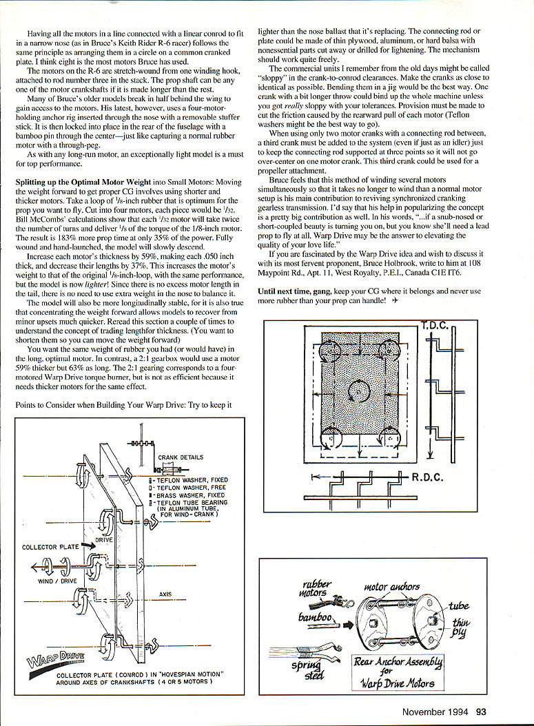
A Diagram is Worth a Thousand Words
Jim Kaman, who did much of the art for this column, looked up "hovespian" (where, I don't know, as it's not in my Webster's Unabridged) and says it comes from Latin, meaning "inexplicable" or "beyond comprehension." Luckily, his drawings and Bruce's photos help explain the "inexplicable."
Study the Warp Drive drawings well; although there are many possible variations, once you understand the concept, you can experiment on your own. Note that putting all the smaller motors' output into a common connecting rod or plate forces them to operate as the one, long optimal motor you are replacing. It's probably better, due to the speed-leveling effect of the mechanism.
Having all the motors in a line connected with a linear conrod to fit in a narrow nose (as in Bruce's Keith Rider R-6 racer) follows the same principle as arranging them in a circle on a common cranked plate. I think eight is the most motors Bruce has used.
The motors on the R-6 are stretch-wound from one winding hook, attached to rod number three in the stack. The prop shaft can be any one of the motor crankshafts if it is made longer than the rest.
Many of Bruce's older models break in half behind the wing to gain access to the motors. His latest, however, uses a four-motor-holding anchor rig inserted through the nose with a removable stuffer stick. It is then locked into place in the rear of the fuselage with a bamboo pin through the center—just like capturing a normal rubber motor with a through-peg.
As with any long-run motor, an exceptionally light model is a must for top performance.
Splitting up the Optimal Motor Weight into Small Motors
To move the weight forward and get proper CG, use shorter and thicker motors. Take a loop of 1/8-inch rubber that is optimum for the prop you want to fly. Cut it into four motors; each piece would be 1/32 inch.
Bill McCombs' calculations show that each 1/32 motor will take twice the number of turns and deliver 1/8 of the torque of the 1/8-inch motor. The result is 183% more prop time at only 35% of the power. Fully wound and hand-launched, the model will slowly descend.
Increase each motor's thickness by 59%, making each 0.050 inch thick, and decrease their lengths by 37%. This increases the motor's weight to that of the original 1/8-inch loop, with the same performance, but the model is now lighter! Since there is no more extra motor length in the tail, there is no need to use extra weight in the nose to balance it.
The model will also be more longitudinally stable, for it is also true that concentrating the weight forward allows models to recover from minor upsets much quicker. Reread this section a couple of times to understand the concept of trading length for thickness.
You want the same weight of rubber you had (or would have) in the long, optimal motor. In contrast, a 2:1 gearbox would use a motor 59% thicker but 63% as long. The 2:1 gearing corresponds to a four-motored Warp Drive torque burner, but is not as efficient because it needs thicker motors for the same effect.
Points to Consider when Building Your Warp Drive
- Try to keep it lighter than the nose ballast that it's replacing.
- The connecting rod or plate could be made of thin plywood, aluminum, or hard balsa with nonessential parts cut away or drilled for lightening. The mechanism should work quite freely.
- The commercial units I remember from the old days might be called "sloppy" in the crank-to-conrod clearances. Make the cranks as close to identical as possible. Bending them in a jig would be the best way. One crank with a bit longer throw would build the whole machine unless you get really sloppy with your tolerances.
- Provision must be made to cut the friction caused by the rearward pull of each motor (Teflon washers might be the best way to go).
- When using only two motor cranks with a connecting rod between, a third crank must be added to the system (even if just as an idler) just to keep the connecting rod supported at three points so it will not go over-center on one motor crank. This third crank could be used for a propeller attachment.
Bruce feels that his method of winding several motors simultaneously so that it takes no longer to wind than a normal motor setup is his main contribution to reviving synchronized cranking gearless transmissions. I'd say that his help in popularizing the concept is a pretty big contribution as well. In his words, "If a sub-nosed or short-coupled beauty is turning you on, but you know she'll need a lead prop to fly at that, Warp Drive may be the answer to elevating the quality of your low life."
If you are fascinated by the Warp Drive idea and wish to discuss it with its most fervent proponent, write to Bruce Holbrook at 108 Maypoint Rd., Apt. 11, West Royalty, P.E.I., Canada C1E 1T6.
Until next time, gang, keep your CG where it belongs and never use more rubber than your prop can handle!
Transcribed from original scans by AI. Minor OCR errors may remain.

