
Free Flight: Sport & Scale
Bill Warner 1370 Monache Ave. Porterville, CA 93257
HOT: Compressed-air motors on the rise
The hottest new development on the model scene seems to be one of the oldest—the compressed-air motor. Free Flight Scale has passed through some power fads: in the sixties it was the 1/4A gas engine, in the seventies CO2, electric was big in the eighties, and now compressed air seems to be on the rise for the nineties.
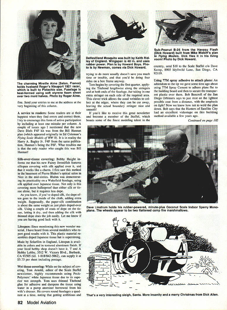
The motor getting much recent attention is the Italian Power Max Z. Doug McHard relates his experiences with this unit in the April and May issues of Aeromodeller. He is averaging minute-and-a-half flights on his Piper Super Cruiser. The motor is rated at seven bars pressure (over 100 psi) and is filled with a hand pump. As the head blows off at nine bars, some reinforcement is needed to help it stay in place when overfilling the clear plastic tank. Doug used the end from a Pentel permanent marker, peening the aluminum sheath around the cylinder and CA'ing the lot together for extra strength. It seems that it's that last little bit of pressure that makes the difference between an average and a spectacular climb!
The Max Z motor is available in the U.S. from Bert Pond, 128 Warren Terrace, Long Meadow, MA 01106 (tel. 1-413/567-5346).
New contest
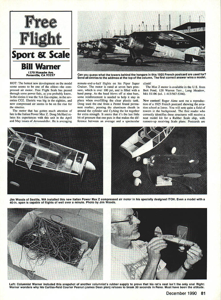
Roger Aime sent a reproduction of a 1925 French postcard showing the aviation school at Istres. You will note quite a field of towers in the background. The first reader who correctly identifies these structures will receive a neat model kit for a Rubber Scale ship, with runners-up receiving Scale plans. Postcards are reproduced here.
Encouraging reader participation (and the occasional mistake)
Some readers are happiest when they find errors. I try to encourage active participation — including at least one deliberate mistake per column. A couple issues ago I mentioned the new Dave Diels F4F kit. Bill Hannan's plan originally appeared in Ed Coleman's Flying Scale Models. WWII reality — Harry Bagley Jr.'s F4F appeared in the same publication; Hannan's is being shown as an F6F. That troubles readers who remember the original identification.
Silk-over-tissue covering
Bobby Haight's new Fairey Swordfish features silkspan covering. Silk applied over tissue works like a charm — I first saw the method in Pierre Bluhm's workshop in the mid-sixties. Bluhm demonstrated its practicality on a Wakefield fuselage using silk applied over Japanese tissue covering — bulletproof. Either silk or tissue alone requires less dope; when you've doped silk, dope tends to go into the cloth, adding extra weight. Supposedly a paper-silk combination is about the same weight as plain doped-over silk. Using a couple coats of dope on the tissue, letting it dry, then adding the silk with thinned dope does the job easily. Let me know if you're having good luck.
Litespan
Since mentioning this new material, several modelers have reported good results. The plastic material resembles doped Japanese tissue and is super-strong. Made by Solarfilm in England, Litespan is available in colors and a textured aluminum finish. If your local hobby shop doesn't have it, try Hobby Lobby, 3512 W. Victory Blvd., Burbank, CA 91505 (tel. 1-818/842-5062). They can supply it for $3.75 per sheet including postage.
Wet-tissue covering (Peck Polymers)
Tom Arnold, editor of the Scale Staffel newsletter, highly recommends using Peck Polymers white Japanese tissue due to its superior wet strength. Tom uses thinned Titebond glue as the adhesive and dampens the tissue using a water pump atomizer (he borrowed his wife's). He begins covering round fuselages by doing the first quadrant, noting that trying to do more usually doesn't save much time or trouble, and that you'd be doing four sides on a box frame anyway.
Tom begins by covering the first quarter, applying Titebond lengthwise along the stringers and at both ends of the fuselage, but taking in one extra stringer on each side of the required area. This trick allows the usual wrinkles to collect at the edges, where they can be cut away, leaving the actual boundary stringer nice and smooth!
If you'd like to receive this great newsletter and become a member of the Staffel, which boasts some of the finest modeling talent in the country, send $10 to the Scale Staffel c/o Dave Kemp, 8905 Idyllwild Lane, San Diego, CA 92119.
Using 77M spray adhesive to attach plans
An addendum to an earlier write-up about using 77M Spray Cement to adhere plans flat to the building board: Bob Beecroft of the San Diego Orbiters says to mist on the lightest possible coat from a distance, with emphasis on light. Now we know how not to weld the plan down. Bob also mentioned that the Hunters of Satellite City had an excellent videotape on building models made available a few years ago.
---
Free Flight: Sport & Scale (continued)
Threadlocker: prevent loose screws and leaks
Have you ever had a screw back out of a flight timer, lost a component, or suffered runaway overruns because screws came loose? Don't let it happen again. For some years now I've been backing out the screws of the flight timer and adding a tiny drop of Loctite 242 Threadlocker compound before installing the timer in a model. I'm particularly faithful with ignition models, as the vibration produced by some of these vintage gasoline burners is ferocious. I also use the procedure to prevent crankcase screws from loosening on radially mounted engines. Threadlocker makes a fine sealant for those red Cox T.D. .020 Free Flight tank mounts, which invariably leak fuel sooner or later.
My tiny bottle of Loctite 242 finally went dry. Not finding any 242 on the hardware-store rack, I latched onto a bottle of Devcon thread-locking compound hoping it would be a fair substitute. So far, so good. The only difference I can find is that the 242 is blue while the Devcon compound is purple; but who cares, as long as it serves the purpose? (I'll probably be pestering mail from some chemical engineer who will write a four-page epistle on the good and bad points of various brands.)
Whichever brand is available in your area, it's a good idea to use some sort of thread-locking compound on all metal-to-metal machine-screw attachments on any engine mountings or flight-timer mechanisms.
The Zeek Chronicles — Part VII
The history of the Zeek design having been summarized in previous chapters, what remains is to record for posterity the flabbed flat-bottom airfoil, B/C class, 575-sq.-in. version. The first five chapters traced the origins of Lew Mahieu's initial 277-sq.-in. single-spar version from 1947 to the mid-fifties, when we finally laid to rest the tooling for the glow-powered A/B kit with Frank Garger of Midwest Models. That covered the Zeeks which incorporated undercambered airfoils.
In the last chapter I doubled back to expound on the flat-bottom-airfoil spin-off designs, which began with the 1/4A kit version, then reintroduced Dan Lutz's 276-sq.-in. Class A, 90-powered derivative of 1951 in three-view form with accompanying model construction information. Should anyone wish to review those previous installments, the following index will save research: August '88, December '88, April '89, June '89, August '89 and June '90. There was also a significant group photo in the October 1990 issue.
My personal quest to obtain a set of plans for the 575 began after discussions prompted by articles I ran in the Central Indiana Aeromodellers newsletter in the late seventies. Dan Lutz eventually got Lew Mahieu's attention, and when the magazine article to record the history of the Zeek was published, quite a mass of material had been collected—yet gaps remained. My hope was that the Zeek history would be put into some orderly fashion—plans that were not available, for example.
Since any full-length article would have been incomplete, and since adding three-views might make the piece too long for a single issue, it was decided to attempt a series of shorter excerpts instead. With this approach it might be possible to generate additional input from knowledgeable readers along the way. Man, did that decision ever produce pay dirt!
The search for plans of the 575 began in earnest when Lyman Armstrong volunteered the names of five individuals who he thought had plan sets at one time or another. After a few months investigating them, however, these leads ran into dead ends. Even Bill Cranford, who had authored the plans, had lost his original tracings in a fire. For a while it appeared that the 575 might never see the light of day again.
In November 1988 Chet Orill wrote to say that he had been following the Zeek chronicles and had a plan set of the 575 that he received from Lew Mahieu at the '53 Nats. Unbelievable! Chet lived in Connecticut. Who would have expected any 575 plans to turn up in New England, of all places? This design had originated in California, where most known plan sets were distributed. Strange things do occur in this hobby.
While the kinship of the 575 with previous kit Zeeks is clearly apparent, the entire model appears sleeker and slimmer. The deep belly of the fuselage is gone, producing the optical effect of a fuselage proportionally longer than its predecessors. The planform also has a somewhat stretched look because of its higher-aspect-ratio wing and stab. Yet the 575 is unmistakably still a Zeek.
The plans recommend a K&B .29 or .32 engine, possibly because Bill Cranford's collaborator on this project was Lew Mahieu himself, who at the time was aiding Bill in producing the kitted Zeeks under the Premium Manufacturing Co. label while simultaneously working at K&B. These engines could be conveniently radially mounted to a 1/4-in. plywood firewall, eliminating the need for metal engine mounts or hardwood motor bearers and saving considerable labor and weight. The plans do mention hardwood beam mounts should the engine utilized require them.
As with any balsa fuselage Zeek, the 575 fuselage box is constructed upside down over the plan. The top and bottom are firm 1/16-in. sheet, the sides 1/8-in. sheet stock. All bulkheads aft of the 5/8-in. plywood firewall are 1/16-in. sheet. The pylon is laminated from 1/8-in. sheet core with the wood grain running vertically. The sides are 3/4-in. sheet core with the grain running horizontally. Wing and stab platforms are 1/8-in. sheet. Of course, the pylon is not permanently located until both the wing and stab are totally completed and covered, so that the correct longitudinal balance point can be established.
The flat-bottomed airfoil of the 575 wing facilitates construction, as all outlines and spars can be pinned down to the plans and the ribs subsequently added. This is a good deal compared with the internal spars required for the undercambered airfoils on the A/B kit versions.
Bill of materials for the wing:
- Leading edge (LE): 1/4 x 3/4 in.
- Trailing edge (TE): 1/4 x 1 in.
- Ribs: 1/2-in. sheet ribs
- Wing tip outlines: 1/4-in. sheet
- Tip spars: 1/4 x 5/8 in.
- Top sheeting: 1/8-in. sheet cut to the standard 3-in. width
The space between the two center ribs is planked on the top only to facilitate retaining the wing to the wing platform with rubber bands.
The stab construction is similar to the wing. The outline and spar are tacked over the plan and the 1/4-in. sheet ribs added last. The contoured outlines are 1/8-in. sheet; the LE is a 1/4 x 3/8-in. block with a 1/8-in. spacer. The midrib, with the third rib from each end, is spaced over the two center ribs to the 1/4-in. sheet vertical fin, and the top of the LE is planked with 1/8-in. sheet as shown.
Actually, the entire model is quite simple and quick to build. Mahieu and Cranford took obvious measures to use standard wood sizes and building techniques. As Bill Cranford indicated previously, a number of the plan sets were originally distributed to assess the marketability of a possible B/C 575 kit. For whatever reasons, the kit was never produced commercially.
In the course of writing the Zeek chronicles, a number of entertaining and interesting facts have emerged, and I have acquired a considerable inventory of full-size Zeek plans. Should anyone require information in this regard, a large SASE will get you a listing.
That's it! There ain't no more. Till next time, see you downwind!
Transcribed from original scans by AI. Minor OCR errors may remain.

