
FREEWING A-10 THUNDERBOLT II
Jay Smith jays@modelaircraft.org
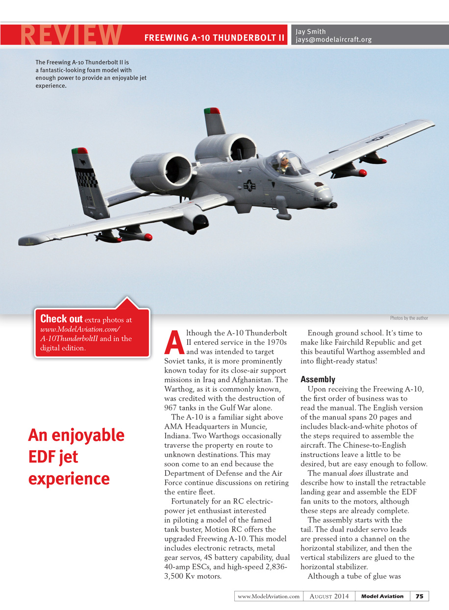
An enjoyable EDF jet experience
Although the A-10 Thunderbolt II entered service in the 1970s and was intended to target Soviet tanks, it is more prominently known today for its close-air support missions in Iraq and Afghanistan. The Warthog, as it is commonly known, was credited with the destruction of 967 tanks in the Gulf War alone.
The A-10 is a familiar sight above AMA Headquarters in Muncie, Indiana. Two Warthogs occasionally traverse the property en route to unknown destinations. This may soon come to an end because the Department of Defense and the Air Force continue discussions on retiring the entire fleet.
Fortunately for an RC electric-power jet enthusiast interested in piloting a model of the famed tank buster, Motion RC offers the upgraded Freewing A-10. This model includes electronic retracts, metal-gear servos, 4S battery capability, dual 40-amp ESCs, and high-speed 2,836–3,500 Kv motors.
Enough ground school. It's time to make like Fairchild Republic and get this beautiful Warthog assembled and into flight-ready status!
Assembly
Upon receiving the Freewing A-10, the first order of business was to read the manual. The English version spans 20 pages and includes black-and-white photos of the steps required to assemble the aircraft. The Chinese-to-English instructions leave a little to be desired, but are easy enough to follow.
The manual does illustrate and describe how to install the retractable landing gear and assemble the EDF fan units to the motors, although those steps were already completed at delivery.
The assembly starts with the tail. The dual-rudder servo leads are pressed into a channel on the horizontal stabilizer, and then the vertical stabilizers are glued to the horizontal stabilizer. Although a tube of glue was included with the model, I chose to use Beacon Foam-Tac because it has proven to be a reliable adhesive.
The dual-rudder servo leads are plugged into the leads at the bottom of the fuselage and the entire tail is held in place by two screws. The elevator is operated by two pushrods, one on each side, that are connected to the preinstalled control horns via clevises. I noticed that one of the two screws attaching one of the control horns to the elevator had not been threaded into the plastic plate that sandwiches the elevator. I easily corrected this, but issues like that are why it is important to check these items before flight.
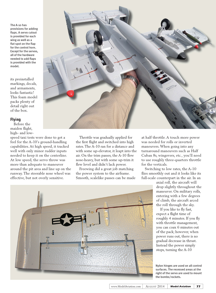
The A-10 does provide a flap option and a servo cutout is provided for each wing. Because the flaps are optional, they do not use nylon hinges like the ailerons and are hinged only with foam. I opted to fly the A-10 without flaps, knowing that adding them later is an option.
The armament included with the A-10 consists of nine rockets/bombs. The large bomb in the center of the wing is attached with magnets, while the other eight, four on each wing, mount to hardpoints on the wings. I decided to only attach four of the bombs/rockets to save weight and make it easier to install flap servos if I later decided to add them. Leaving off the four pieces of armament saved 0.9 ounces.
The main wing attaches to the fuselage using two screws that screw into a plywood plate in the fuselage. Although two pilot holes were predrilled, mine did not align with the screw holes in the wing. I marked the location of the holes and drilled my own pilot holes with a 5/64-in. pin vise. I carefully drove the screws in the pilot holes, removed them, and used thin CA to harden the wood, being careful not to get any on the foam. The wing was then easily attached. Two fins are added to the bottom sides of the fuselage after the wing is attached to add additional scale appeal.
All of the mounting points, including the tail, wing, and power pod, utilize a plastic insert that ensures the screws can be securely attached without digging into the foam or creating a weak point.
Before attaching the motor pod, I confirmed that both motors were operating in the proper direction. If they are not, simply disconnect two of the three motor wires on either motor and swap the two connections.
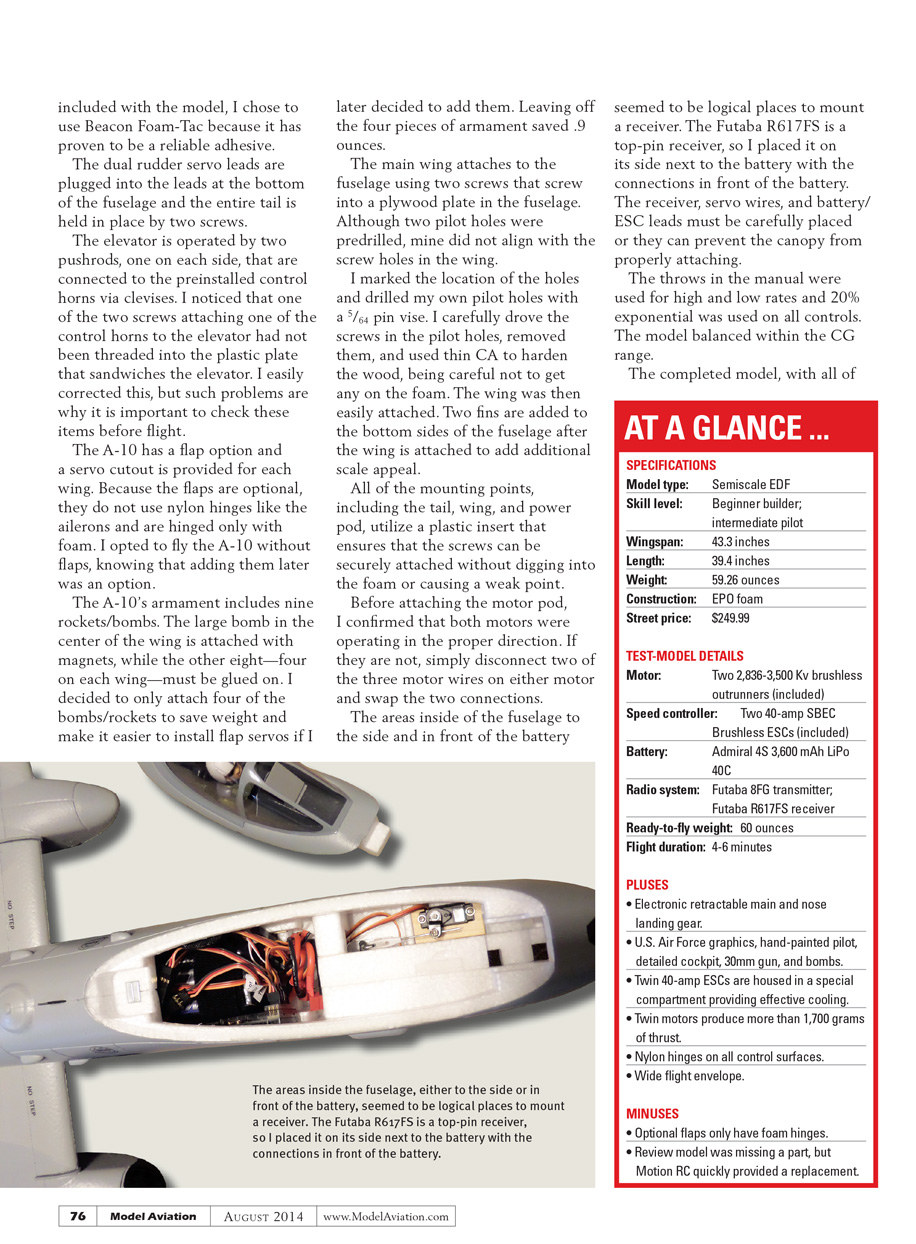
The areas inside the fuselage to the side and in front of the battery seemed logical places to mount a receiver. The Futaba R617FS is a top-pin receiver, so I placed it on its side next to the battery with the connections in front. The receiver, servo wires, and battery/ESC leads must be carefully placed or they can prevent the canopy from properly attaching.
I used the throws recommended in the manual for high and low rates and set 20% exponential on all controls. The model balanced within the CG range.
The completed model, with all of its pre-applied markings, decals, and armaments, looks fantastic. This foam model packs plenty of detail right out of the box.
Flying
Before the maiden flight, high- and low-speed taxi tests were done to get a feel for the A-10's ground-handling capabilities. At high speed, it tracked well with only minor rudder inputs needed to keep it on the centerline. At low speed, the servo throw was more than adequate to maneuver around the pit area and line up on the runway. The steerable nose wheel was effective, but not overly sensitive.
Throttle was gradually applied for the first flight and I switched into high rates. The A-10 ran for a distance and with some up-elevator it leapt into the air. On the trim passes, the A-10 flew nose-heavy, but with some up-trim it flew level and didn't lack power. Freewing did a great job matching the power system to the airframe. Smooth, scale-like passes can be made at half throttle. A touch more power was needed for rolls or inverted maneuvers. When going into any turnaround maneuvers such as Half Cuban 8s or wingovers, you'll need to use roughly three-quarters throttle for the verticals.
Switching to low rates, the A-10 flies smoothly and it looks like its full-scale counterpart in the air. In an axial roll, the aircraft will drop slightly throughout the maneuver. On military rolls, entering with a few degrees of climb, the aircraft arced the roll through the sky.
If you like to fly fast, expect a flight time of roughly 4 minutes. With throttle management you can coax about 6 minutes out of the pack; however, when power runs out, there is no gradual decrease in thrust. Instead the power simply stops, turning the A-10 into a glider. To ensure you have power for your landings, set your timer and use it vigilantly.
Even without flaps, the A-10 slows to a manageable landing speed and seems happiest when touchdown happens under power, using a combination of throttle and slight up-elevator to control descent. This method provides a nice three-point landing and a pleasing rollout.
Conclusion
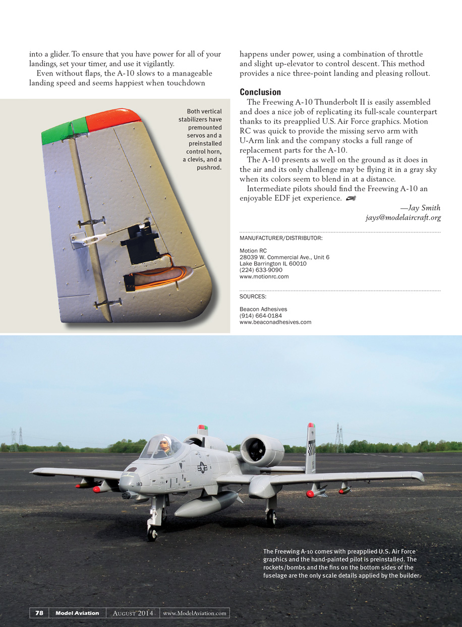
The Freewing A-10 Thunderbolt II is easily assembled and does a nice job of replicating its full-scale counterpart thanks to its pre-applied U.S. Air Force graphics. Motion RC was quick to provide the missing servo arm with U-Arm link, and the company stocks a full range of replacement parts for the A-10.
The A-10 presents as well on the ground as it does in the air; its only challenge may be flying it in a gray sky when its colors seem to blend in at a distance.
Intermediate pilots should find the Freewing A-10 an enjoyable EDF jet experience.
—Jay Smith jays@modelaircraft.org
Transcribed from original scans by AI. Minor OCR errors may remain.

