
French Wench
Powered by a Cox Tee Dee, this above-average Free Flight was designed to meet a list of demanding right-on requirements—thus avoiding the outmoded method of bending the airframe with a series of modifications.
Designed by Dale E. Mateer
Text by Mateer and Jerry W. Barnette
A NEW MODEL design must have a reason for being: better performance, better construction, or a myriad of other reasons. Another truism is that sooner or later most free fliers get the itch to "roll their own," to advance the Free-Flight state of the art by designing their own flying machine. Thus, the birth of the "French Wench."
A systematic approach was taken with this new design. Rather than drawing a nice, sporty-looking airplane followed by countless modifications and redesigns to make it perform adequately, a form-follows-function approach was adopted. That is, a set of design objectives was established and the features that satisfied these objectives would determine what the final design would look like. With this approach in mind, the following design objectives were established:
- Light weight. A one-pound brick flies better than a 20-pound brick.
- Fast climb. Because we fly mostly Category II contests on the East Coast, a brisk climb is required for these short engine runs as well as for fly-off flights.
- Good glide. A good glide is a prime requirement of any contest Free-Flight model.
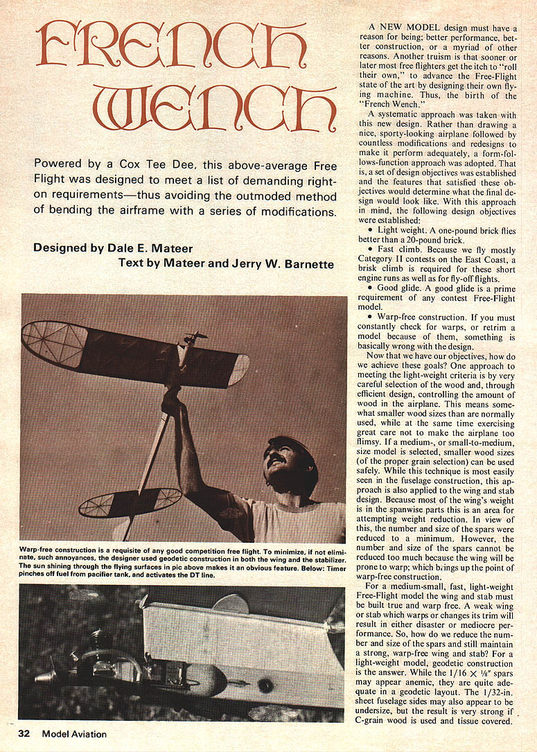
- Warp-free construction. If you must constantly check for warps, or retrim a model because of them, something is basically wrong with the design.
Now that we have our objectives, how do we achieve these goals? One approach to meeting the light-weight criteria is by very careful selection of the wood and, through efficient design, controlling the amount of wood in the airplane. This means somewhat smaller wood sizes than are normally used, while at the same time exercising great care not to make the airplane too flimsy. If a medium- or small-to-medium-size model is selected, smaller wood sizes (of the proper grain selection) can be used safely. While this technique is most easily seen in the fuselage construction, this approach is also applied to the wing and stab design. Because most of the wing's weight is in the spanwise parts this is an area for attempting weight reduction. In view of this, the number and size of the spars cannot be reduced to a minimum. However, the number and size of the spars cannot be reduced too much because the wing will be prone to warp; which brings up the point of warp-free construction.
For a medium-small, fast, light-weight Free-Flight model the wing and stab must be built true and warp free. A weak wing or stab which warps or changes its trim will result in either disaster or mediocre performance. So, how do we reduce the number and size of the spars and still maintain a strong, warp-free wing and stab? For a light-weight model, geodetic construction is the answer. While the 1/16 x 1/8 spars may appear anemic, they are quite adequate in a geodetic layout. The 1/32-in. sheet fuselage sides may also appear to be undersize, but the result is very strong if C-grain wood is used and tissue covered. In addition to a slight (theoretical) advantage, elliptical tips add strength in this area and help reduce weight as opposed to use of rectangular tips.
The fast-climb requirement is met by the overall wing size (248 sq. in. area), use of a thin airfoil, and light-weight construction. Of course, a hot Cox Tee Dee fed with high nitro fuel, pressurized by a pacifier, turning a small prop also helps. The use of a rear fin, while not directly adding speed to the climb, contributes to a better power pattern. As for the glide requirement, achieving the light-weight objective and having a 5 1/4 ounce all-up airplane helps the glide considerably. Of course, other design factors also contribute; for example a moderate aspect ratio of 7.8 to 1, a 31 percent stab with an efficiently sized tail moment, etc. Theory and logic is all very good, but the question is, does it work? In the case of the French Wench the answer is yes. The design does result in a very light-weight model which is warp free, has a floating glide, and has a most impressive rapid climb. And it wins contests, another nice feature.
To further prove the validity of the concept, the design was scaled up to a B-Gas size (560 sq. in., 24 oz., K&B .29 rear rotor) as shown in the photos. The B-job did prove the soundness of the design as it is an even more impressive performer. It should be noted that despite the rapid climb the power pattern is very safe in both sizes.
And the name, "French Wench?" Originally, the design was nameless. After the model flew so well and won a few contests it was decided to give the design a name of its own. But what to call it? Much thought and research went into finding an appropriate, descriptive, pleasant sounding name for the new bird. Friends were asked to contribute names. Weeks went by without finding the right name. Then one evening during a hangar flying session with some friends, the wife dropped in with some coffee. Hearing of the name dilemma, the wife said "French Wench." One of the great unwritten rules is that one never argues with the bringer of coffee or the wife, so....
Construction
The wing is straight forward in construction. Using a plywood or metal template, cut out all straight and geodetic ribs from light-weight C-grain stock. Cut the 1/4-in., 1/8-in., and 1/16-in. wide strips for the tip leading and trailing edge laminations. Notch the trailing edges for the main panels and pin to the plans. Pin the leading edges and the lower spar to the plans. Medium-hard stock should be used for main panel leading edges, trailing edges and spars. Use Hot Stuff adhesive or Tite Bond glue for all construction. To begin construction, laminate the tip leading and trailing edges. Establish the lamination guide by placing pins about 1/2-in. apart on plans around the inner trailing and leading edge outlines. Pin the balsa tip blocks in place. Bend the first lamination around the pins and glue to the tip block with Hot Stuff. Continue this procedure, adding one strip at a time until all laminations are glued in place.
Pin lower tip spar to the plans. Glue in all straight ribs (except those at the dihedral breaks). Add the two main spars, the geodetic ribs and the remaining top spar. Remove main and tip panels from plans and sand to shape, using the spars in the tip panels as a guide. Prepare to join the panels by sanding the leading edges and trailing edges to the proper angles. Epoxy in dihedral and polyhedral joints at the tips using special end of panels. Add the plywood dihedral braces. The main ribs should have no warps while the tips should have a small amount of wash-out. Add the remaining straight and geodetic ribs at the dihedral breaks. Glue in center planking and gussets.
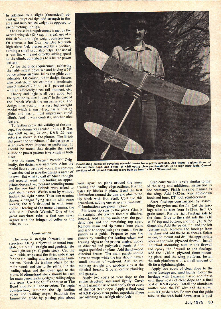
Apply two coats of clear dope to the entire structure and sand lightly. Cover with Japanese tissue and apply three coats of thinned clear dope. Apply a final coat of K&B epoxy clear paint, especially if you are planning to use high-nitro fuels.
Stab construction is very similar to that of the wing and additional instruction is not necessary. Finish in same manner as the wing. Add 1/32-in. wire hold-down hook and brass DT hook reinforcement.
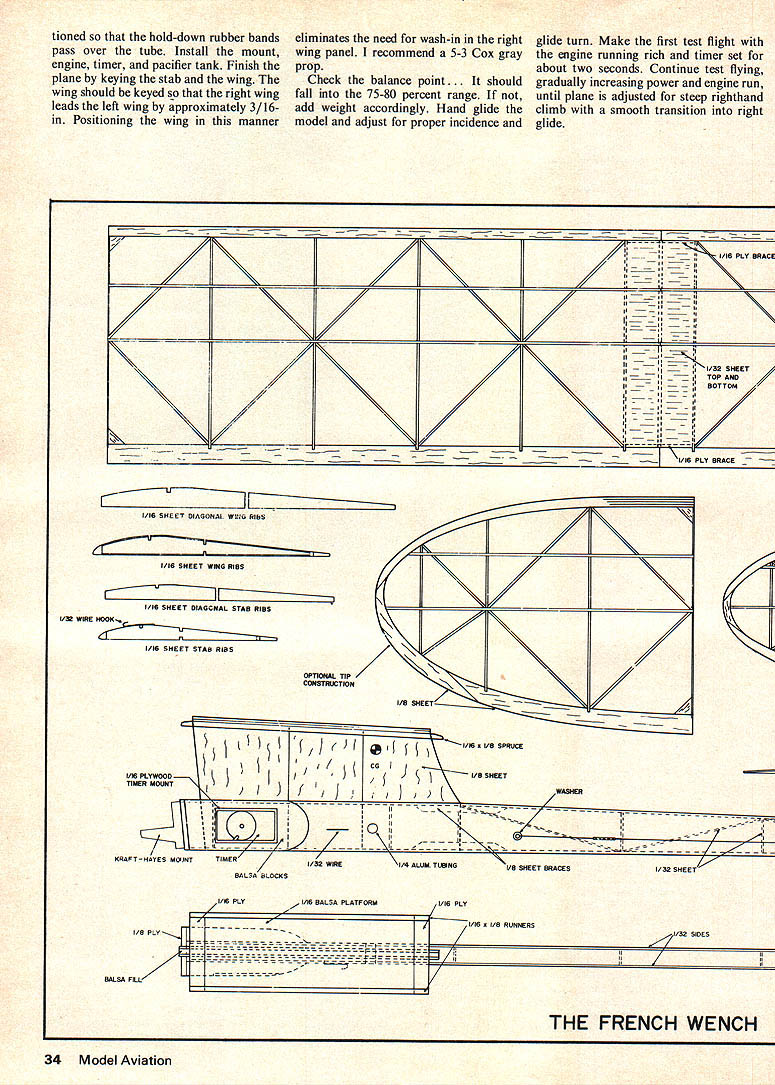
Start fuselage construction by assembling the pylon and the fin. Cut the fuselage sides to size from 1/32-in. firm C-grain stock. Pin the right fuselage side to the plans. Glue to the right side the 1/16 x 3/8 top and bottom, and the 1/16 x 3/8 diagonals. Add the pylon, fin, and the left fuselage side. Remove the fuselage from the plans and sand the panels and planks to shape. Select an engine mount and drill the mounting holes in the pylon. Install the DT line hold-down hook and the auxiliary hook with epoxy. Cut and glue the firewall and epoxy the firewall to the fuselage. Add the 1/16-in. plywood motor-mounting plate, and the wing platform. Install the stab platform with a small amount of glue for a righthand glide.
Apply two coats of clear dope to the entire fuselage and sand lightly. Cover the fuselage with Japanese tissue and finish with three coats of clear dope and a final coat of K&B epoxy. Install the aluminum snuffer tube, the DT wire and the aluminum DT guide tubes. Be sure that the guide tube in the stab hold down area is posi- tioned so that the hold-down rubber bands pass over the tube. Install the mount, engine, timer, and pacifier tank. Finish the plane by keying the stab and the wing. The wing should be keyed so that the right wing leads the left wing by approximately 3/16-in. Positioning the wing in this manner eliminates the need for wash-in in the right wing panel. I recommend a 5-3 Cox gray prop.
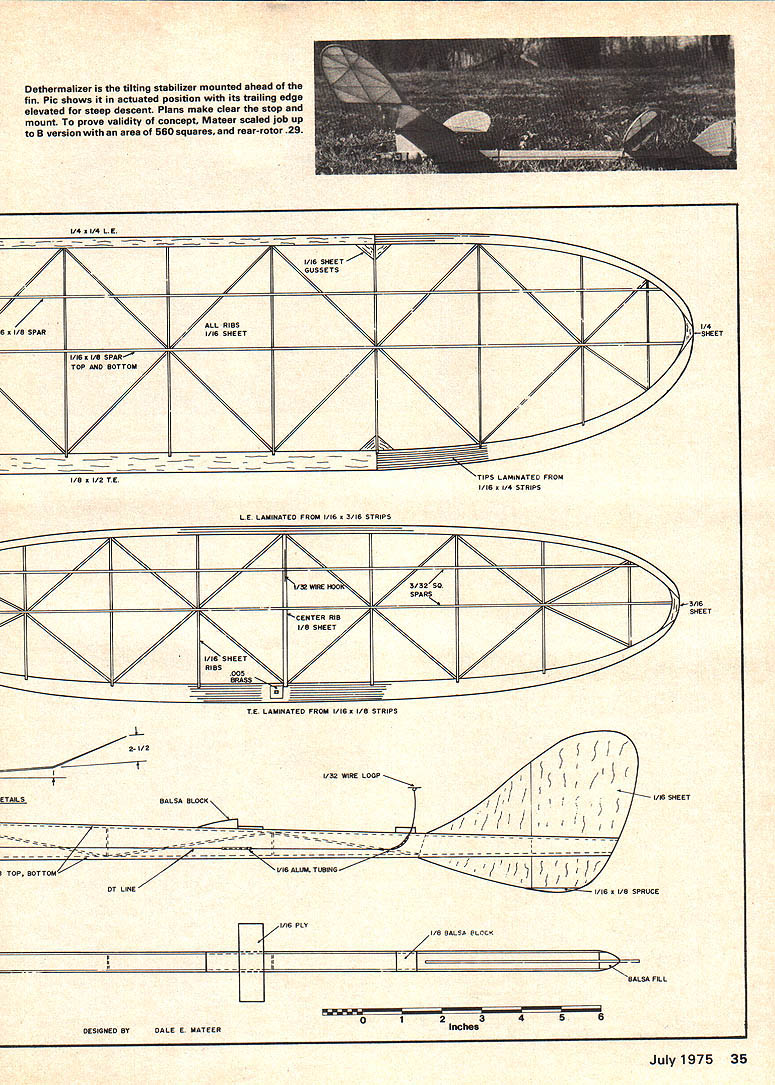
Check the balance point . . . It should fall into the 75-80 percent range. If not, add weight accordingly. Hand glide the model and adjust for proper incidence and glide turn. Make the first test flight with the engine running rich and timer set for about two seconds. Continue test flying, gradually increasing power and engine run, until plane is adjusted for steep righthand climb with a smooth transition into right glide. Dethermalizer is the tilting stabilizer mounted ahead of the fin. Pic shows it in actuated position with its trailing edge elevated for steep descent. Plans make clear the stop and mount. To prove the validity of the concept, Mateer scaled the job up to a B version with an area of 560 square inches, and rear-rotor .29.
Transcribed from original scans by AI. Minor OCR errors may remain.

