
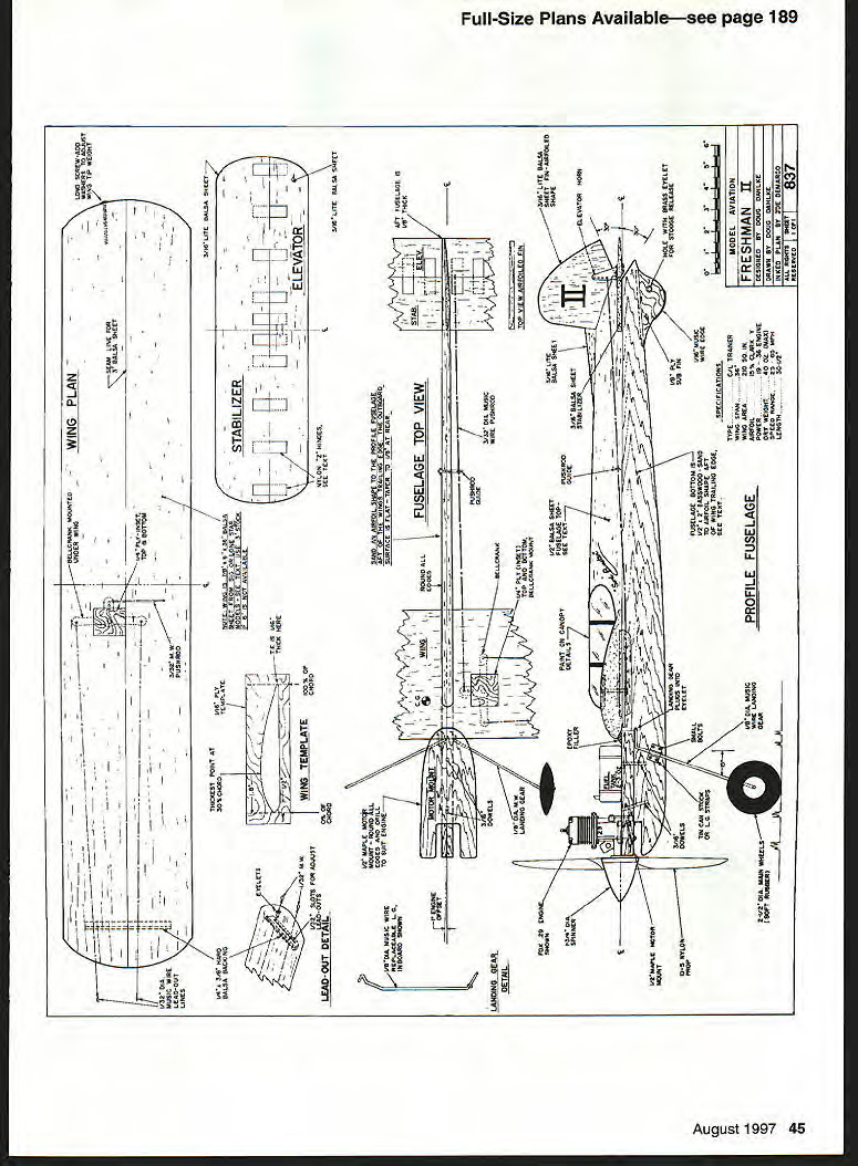
FRESHMAN II
- Doug Dahlke
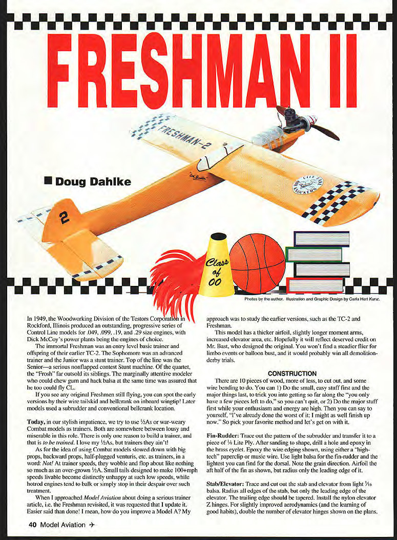
In 1949, the Woodworking Division of the Testors Corporation in Rockford, Illinois produced an outstanding, progressive series of Control-Line models for .049, .099, .19, and .29 size engines, with Dick McCoy's power plants being the engines of choice.
The immortal Freshman was an entry-level basic trainer and offspring of their earlier TC-2. The Sophomore was an advanced trainer and the Junior was a stunt trainer. Top of the line was the Senior — a serious non-flapped contest Stunt machine. Of the quartet, the "Frosh" far outsold its siblings. The marginally attentive modeler who could chew gum and hack balsa at the same time was assured that he too could fly CL.
If you see any original Freshmen still flying, you can spot the early versions by their wire tailskid and bellcrank inboard wingtip. Later models used a subrudder and conventional bellcrank location.
Today, in our stylish impatience, we try to use 1/2As or war-weary Combat models as trainers. Both are somewhere between lousy and miserable in this role. There is only one reason to build a trainer, and that is to be trained. I love my 1/2As, but trainers they ain't.
As for the idea of using Combat models slowed down with big props, backward props, half-plugged venturis, etc., as trainers, in a word: Not! At trainer speeds, they wobble and flop about like nothing so much as an over-grown 1/2A. Small tails designed to make 100+ mph speeds livable become distinctly unhappy at such low speeds, while hot-rodded engines tend to balk or simply stop in their despair over such treatment.
When I approached Model Aviation about doing a serious trainer article, i.e., the Freshman revisited, it was requested that I update it. Easier said than done! I mean, how do you improve a Model A? My approach was to study the earlier versions, such as the TC-2 and Freshman.
This model has a thicker airfoil, slightly longer moment arms, increased elevator area, etc. Hopefully it will reflect deserved credit on Mr. Bast, who designed the original. You won't find a steadier flier for limbo events or balloon busts, and it would probably win all demolition-derby trials.
CONSTRUCTION
There are 10 pieces of wood, more or less, to cut out, and some wire bending to do. You can:
- Do the small, easy stuff first and the major things last, to trick you into getting so far along that you "must have" a few pieces left to do, so you can't quit; or
- Do the major stuff first while your enthusiasm and energy are high. Then you can say to yourself, "I've already done the worst of it; I might as well finish up now."
So pick your favorite method and let's get on with it.
Fin-Rudder
Trace out the pattern of the subrudder and transfer it to a piece of 1/8" lite ply. After sanding to shape, drill a hole and epoxy in the brass eyelet. Epoxy the wire edging shown, using either a "high-tech" paperclip or music wire. Use light balsa for the fin-rudder and the lightest you can find for the dorsal. Note the grain direction. Airfoil the aft half of the fin as shown, but radius only the leading edge of it.
Stab/Elevator
Trace and cut out the stabilizer and elevator from light 3/16" balsa. Radius all edges of the stabilizer, but only the leading edge of the elevator. The trailing edge should be tapered. Install the nylon elevator Z-hinges. For slightly improved aerodynamics (and the learning of good habits), double the number of elevator hinges shown on the plans.
Fuselage
Spend some time chasing around your local lumber yards for a decent piece of basswood 1/2" x 2" x 30". (White pine could be substituted, if the weight does not exceed the provided figures.) Once the bottom of the fuselage is squared off, find the heavy end of the wood. Carefully draw a fine line at the 15-inch mark and balance your fuselage-to-be on a knife edge. The heavy end is the front.
Trace the fuselage outline on the wood and cut it out. Slot the bottom for insertion of the subrudder. Trace and cut out the engine mount unit from 1/2" maple. Notch the front to fit the engine you plan to use and drill for the engine bolt holes. Radius the corners of the mount unit (otherwise the paint won't stick well; sharp edges promote chipping).
Use a sharp, small carpenter's plane to airfoil the rear half of the fuselage, starting at the trailing edge of the wing. Gently curve the inboard portion of the fuselage, but leave the outboard surface flat. The fuselage should be about 1/8" thick at the aftmost point. It is important to get rid of this excess weight—your model will be tail-heavy and will not fly well if you leave out this step!
Sand/radius all parts of the fuselage, except where there is (or will be) a glue joint. For the top balsa portion of the fuselage, use the same procedure as you did for the bottom. Don't forget to notch the fuselage where the stabilizer fits in.
Wing
Required timber is 7/8" x 6" x 36" balsa. Mike Pratt of Sig or Riley Wooten of Lone Star Models will happily supply you with the required balsa timber for a reasonable fee. If a one-piece six-inch slab is not available, you'll need to butt-join two pieces of three-inch stock. For additional strength, 1/4" sheet could be laminated; this would waste less wood but would increase weight somewhat.
My wing (two pieces of three-inch stock) weighed 400 grams in slab form. Find the heavy end of the slab and make that the outboard wing. Weighing wood in order to position it as we've just done has a double benefit:
- You get "free" tip weight, in the sense of it being effective tip weight.
- The heavier, denser wood is stronger, and the outboard wing catches more abuse than the inboard.
Make your airfoil template from soft aluminum or plywood. You'll want to draw a bunch of lines on the wing slab before you start cutting:
- Fore/aft centerline.
- Tip-to-tip underside line spaced 1/2" back from edge and parallel with the leading edge.
- Tip-to-tip topside at the point of max thickness, spaced 1.8" back from the edge.
- Tip-to-tip trailing edge on aft edge, showing how much to thin.
- A tip-to-tip line on front edge showing where upper and lower camber meet.
- The airfoil outline on each wingtip edge.
- The wingtip rounding outline as seen in planform.
After the lines are drawn, use your carpenter's plane, then a rasp, and progressively finer grades of sandpaper to shave and shape the wing to airfoil shape. Creative folks will make a concave sanding block, using the top portion of the airfoil template. Once you get into hacking away at the wing, you will be amazed at just how much rubble a few ounces of balsa can make when shaved down with a plane! (Wear a dust filter when sanding.)
Wipe the entire wing down with a fairly damp rag—enough to lightly wet the surface of the wood and raise the grain. Allow to dry and sand with 400-grit paper. This is a light way to finish a model and is a method you should use from now on.
If you want to pick up additional wing area and change the appearance a bit, you could add what's known as stationary flaps. At about 1-1/4" wide at the root, tapering to nothing at the tip, you'll gain about 18 square inches, which will be mainly effective during takeoff and landings.
Assembly
Epoxy the finished subrudder in place by lightly clamping the fuselage upside down in a padded vise while allowing it to dry. Align and epoxy the engine-mount unit in place with not more than 1-1/2 degrees of outboard engine offset. (It will fly with no offset, as well.) Use slow-curing epoxy here. Be absolutely certain the mount unit is perpendicular to the lower half of the fuselage.
When all is dry, drill holes for the 3/16" dowel retaining pins to help hold the mount unit to the fuselage bottom. Epoxy the pins in place. Epoxy the wing in place, being certain it is parallel with the top of the engine-mount unit.
Glue the fin, dorsal fin, and top of the fuselage into the unit now using aliphatic-resin glue (Titebond, Sig-Bond, etc.). When dry, fill and sand smooth. Titebond the top half of the fuselage to the lower half. The pushrod uses two L-bends, one on each end; and although soldered washers are used to prevent rubbing against the wood parts, the solder joint may fail without danger to the model, as the ends are simply too long to fall out.
Once the bends are as close to plan specs as possible, remaining length differences are made up by moving the stabilizer fore and aft as needed before gluing in place. Slot the inboard wing and epoxy the line guide in place, followed by the hard balsa backing. Fasten a wood screw into the tip. Add washers to give about 5/8–3/4 ounce total tip weight, which should be a tad too much. To raise the wingtip during flight, remove washers one at a time so that the wing is level.
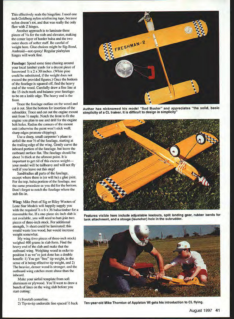
Epoxy the landing gear eyelets in place.
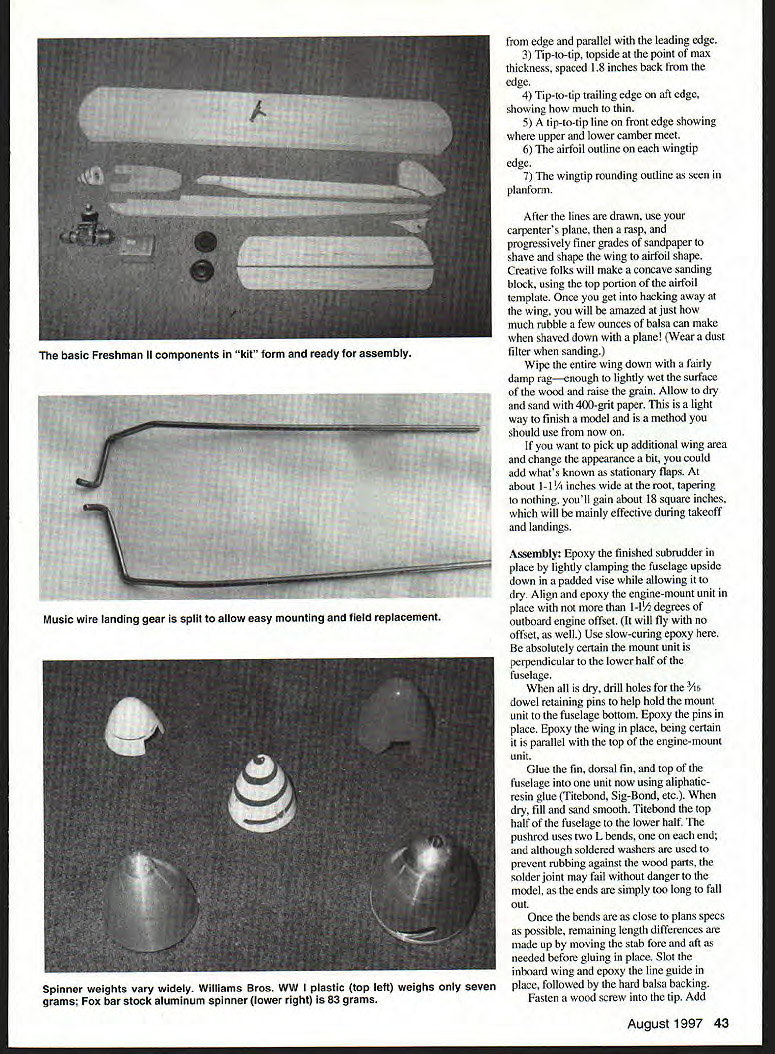
The reason for staggered, in-line gear mount holes is because the fuselage is too narrow to fit both in the same hole. The gear system is a two-piece, detachable, split type which allows easy on-field replacement of individual wires if, perchance, a beginner should bend the gear!
General Freshman II weights (in grams):
- Wing slab: 420
- Leadout guide: 6
- Fuselage bottom (profiled only, not airfoiled): 122
- Fuselage top (profiled only, not airfoiled): 19
- Maple engine mount unit (sanded only): 73
- Stabilizer slab: 10
- Elevator slab: 7
- Fin slab: 4
- Subrudder: 3
The original Freshman used two-piece cross-grained bushed maple wheels. Why not? Wood wheels are as cheap, light, and tough as a microwave sandwich. The plans suggest soft rubber/plastic wheels, at a weight penalty. This is purely for crash resistance.
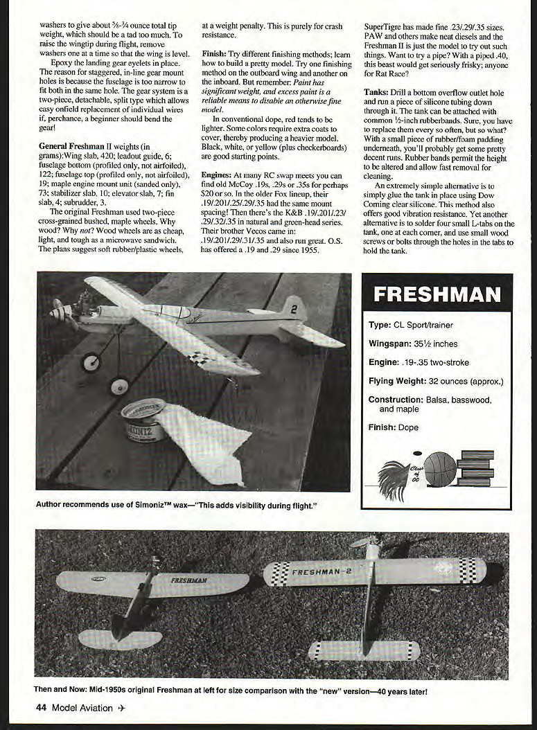
Finish: Try different finishing methods; learn how to build a pretty model. Try one finishing method on the outboard wing and another on the inboard. But remember: paint has significant weight, and excess paint is a reliable means to disable an otherwise fine model.
In conventional dope, red tends to be lighter. Some colors require extra coats to cover, thereby producing a heavier model. Black, white, or yellow (plus checkerboards) are good starting points.
Engines: At many RC swap meets you can find old McCoy .19s, .29s or .35s for perhaps $20 or so. In the older Fox lineup, their .19/.20/.25/.29/.35 had the same mounting spacing. Then there's the K&B .19/.20/.21/.23/.29/.32/.35 in natural and green-head series. Their brother Vecos came in .19/.20/.29/.31/.35 and also run great. O.S. has offered a .19 and .29 since 1955.
SuperTiger has made fine .23/.29/.35 sizes. PAW and others make neat diesels and the Freshman II is just the model to try out such things. Want to try a pipe? With a piped .40, this beast would get seriously frisky; anyone for Rat Race?
Tanks: Drill a bottom overflow outlet hole and run a piece of silicone tubing down through it. The tank can be attached with common 1/2" rubber bands. Sure, you have to replace them every so often, but so what? With a small piece of rubber/foam padding underneath, you'll probably get some pretty decent runs. Rubber bands permit the height to be altered and allow fast removal for cleaning.
An extremely simple alternative is to simply glue the tank in place using Dow Corning clear silicone. This method also offers good vibration resistance. Yet another alternative is to solder four small L-tabs on the tank, one at each corner, and use small wood screws or bolts through the holes in the tabs to hold the tank.
FRESHMAN (SPECIFICATIONS)
- Type: CL sport/trainer
- Wingspan: 35-1/2 inches
- Engine: .19–.35 two-stroke
- Flying weight: 32 ounces (approx.)
- Construction: balsa, basswood, and maple
- Finish: dope
CONSTRUCTION (ALTERNATE/CONDENSED)
Ten pieces of wood—less cutting out and some wire bending—can make a small, easy-to-build model. First major things last: a trick is that when you get fairly far along and have a few pieces left you can't quit. Two major points: first, enthusiasm and energy are high; you can say to yourself "I've already done the worst; I might as well finish up now." So pick your favorite method and let's get on with it.
Rudder
Trace out the pattern for the sub-rudder and transfer the piece to 1/16" lite ply. After sanding to shape, drill the hole and epoxy in a brass eyelet. The epoxy wire edging shown may be made using either a high-tech paperclip or music wire. Use the lightest balsa you can find for the fin/rudder and note grain direction. The airfoil of the aft half of the fin is shown with a radiused leading edge.
Stab/Elevator
Trace and cut out the stabilizer and elevator from light 3/16" balsa. Radius the edges; the stabilizer leading edge and the elevator trailing edge should be tapered. Install nylon Z-hinges for the elevator. A slightly improved arrangement and good-habit detail—double-numbered elevator hinges—are shown on the plans. Some builders seal the hinge line with 1/4" Goldberg nylon reinforcing tape because nylon doesn't rot. Another approach is to laminate the stabilizer and elevator from three pieces—make the center layer a harder balsa and the two outer sheets softer material; be careful of added weight. Glue choices might be Sig-Bond or Ambroid (not epoxy). Regular pin or nylon hinges will work fine.
Fuselage
Spend some time chasing around local lumber yards to find a decent piece of basswood about 3/4" x 3" x 30". White pine can be substituted but its weight may exceed the provided figures. Once the bottom fuselage is squared off, find the heavy end of the wood. Carefully draw a fine line at the 15-inch mark to establish the balance point for the fuselage-to-be (knife-edge heavy end toward the front). Trace the fuselage outline on the wood and cut out. Slot the bottom for insertion of the sub-rudder. Trace and cut out the engine mount unit and notch the front to fit the engine per the plan; use a drill to make the engine bolt holes. Radius the corners of the mount unit—otherwise paint won't stick well and sharp edges promote chipping. Use a sharp small carpenter's plane to airfoil the rear longerons starting at the wing trailing-edge area. Gently curve the inboard portion of the fuselage and leave the outboard surface flat. The fuselage should be about 1/8" thick at the aftmost point. It is important to remove excess weight—if the model is tail-heavy it will not fly well. Sand and radius fuselage parts except where glue joints for the top balsa portion will be made; use the same procedure as for the bottom. Don't forget the notch where the fuselage fits the stabilizer.
Wing
Required timber is 7/8" x 6" x 36" balsa. Mike Pratt, Sig, Riley Wooten, Lone Star Models, and others will happily supply the required balsa for a reasonable fee. A one-piece six-inch slab is available; otherwise you will need to butt-join two pieces of three-inch stock. Additional strength could be obtained by laminating, although that may be unnecessary.
Miscellaneous details
Lead-out, landing gear, and other small details are shown on the full-size plans. Follow the plan details for locations, dihedral, and hardware installation.
Spinner
The plastic spinner shown on the plans is intended to be expendable. There can be up to 2-1/2 ounces difference in spinner weight with middle-sized engines. You can swap spinners to gain or lose nose weight. Heavier spinners also act as flywheels and tend to make starting easier, make the engine run smoother, and reduce vibration in general.
Props
Those using a .19 sport engine should try a 9x4; with a .23 to .25, a 9x5; and the larger .29–.36 stuff should use a 10x5. All nylon props should be stress-relieved for safety reasons by placing the prop in boiling water for 15 minutes, then allowing to cool. The addition of R/C dye in the boiling water will color your prop to match your airplane and improve visibility and safety. The next day, sand the very tip of the prop and add a contrasting color.
Flying
Those with .19-powered models can go with 48- to 52-foot lines for starters. For .23–.25 models, consider 51- to 53-foot lines; .29–.35 models can go out 55–58 feet in length. Yes, a good .19 will fly a model on thick 70-foot lines. Fun, but hardly the thing to do on a regular basis!
If any wood parts become fuel-soaked they can be cleaned by spraying the infected areas with K2r from your local hardware store. Spray on, allow to dry, then brush off the white powder the next day. Repeat as needed until glue will stick again. Amazing stuff!
If you want to jack up the odds of successful flight, a simple thing to do is find a PAMPA (Precision Aerobatic Model Pilots Association) member to help you. Contact Lucky Pyatt, Membership Secretary, at 9629 Hazard Ave., Garden Grove, CA 92844.
I'll answer any questions I can about the Freshman II, but a SASE is requested. I would much enjoy a photo or postcard of your experiences with this aerial dreadnaught—the mighty Freshman II.
— Doug Dahlke 2054 Point Comfort Oshkosh, WI 54901
Transcribed from original scans by AI. Minor OCR errors may remain.

