

For Fun and Test: Profile Models
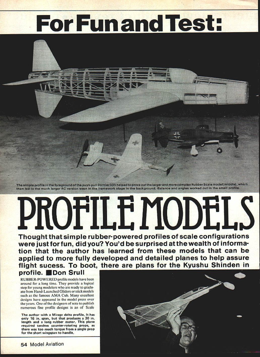
Thought that simple rubber-powered profile scale configurations were just for fun? You'd be surprised at the wealth of information these models can provide — information that applies to more fully developed and detailed planes and helps assure flight success. To boot, plans for the Kyushu Shinden in profile are included here.
Rubber-powered profile models have been around for a long time. They provide a logical step for young modelers who are ready to graduate from hand-launched gliders or stick models such as the famous AMA Cub. Many excellent designs have appeared in the model press over the years.
The author with a Mirage delta profile: it has only a 16 in. span, but that produces a 30 in. length and a long rubber motor. This plane required tandem counter-rotating props because a single prop produced too much torque for the short wingspan to handle.
The popularity of profiles has been enhanced considerably by several fun-type competitive events offered by many free flight clubs. For example, the Flightmasters, the San Diego Orbiters, the DC Maxecuters, and the Flying Aces Club all sponsor profile events for scale catapult gliders and scale rubber-powered models. Flying, rather than scale detail, is the name of the game.
Another use for these skinny models (also known as No-Cals) is as powered test vehicles for new, untried, or unconventional designs. A profile version of a new design can help determine whether it will be suitable for a more elegant model with respect to stability. Perhaps more important, a profile model can also help determine the proper location of the center of gravity (C.G.), the necessary wing-stabilizer angular difference, the correct thrust angle, minimum dihedral, and minimum stabilizer and vertical fin sizes.
That's not bad for a small investment in time and materials. These results are not just appropriate for rubber-powered scale models but can also be helpful for powered free flight scale and radio-control scale models.
During recent years I have built several dozen profile models both for entry in No-Cal contests and as test beds for unusual scale configurations. Delta wings, flying wings, canards, pushers, and tandem twin-engine configurations have all been tried. One of our club members built and mastered the unusual Blohm & Voss asymmetrical configuration. All of this could have been done with fully built-up models, of course, but at a tremendous investment in time (and goodness knows how much more cussing).
With each of these profile test models it was possible to determine with fair accuracy what design deviations from true scale were necessary, if any, and what the complete trim arrangements were that produced good, stable flight performance. In one case, for a flying-wing design, it was found that the basic configuration was a real turkey; the darn thing had problems in every way imaginable — and some that weren't. This saved a lot of further wasted time and frustration.
On the plus side, I had particularly good luck with profile-model tests of a twin-engined push-pull Dornier Do 335. Its potential seemed much better than I had imagined. I then built a larger built-up rubber model of the Dornier and subsequently a 1/2-in. RC scale model of the same bird. The profile model provided good estimates of the wing/stab angular difference, thrust angles, and dihedral requirements for the larger rubber model. As a result, very minor adjustments were required after the larger model was built. The RC project similarly benefited.
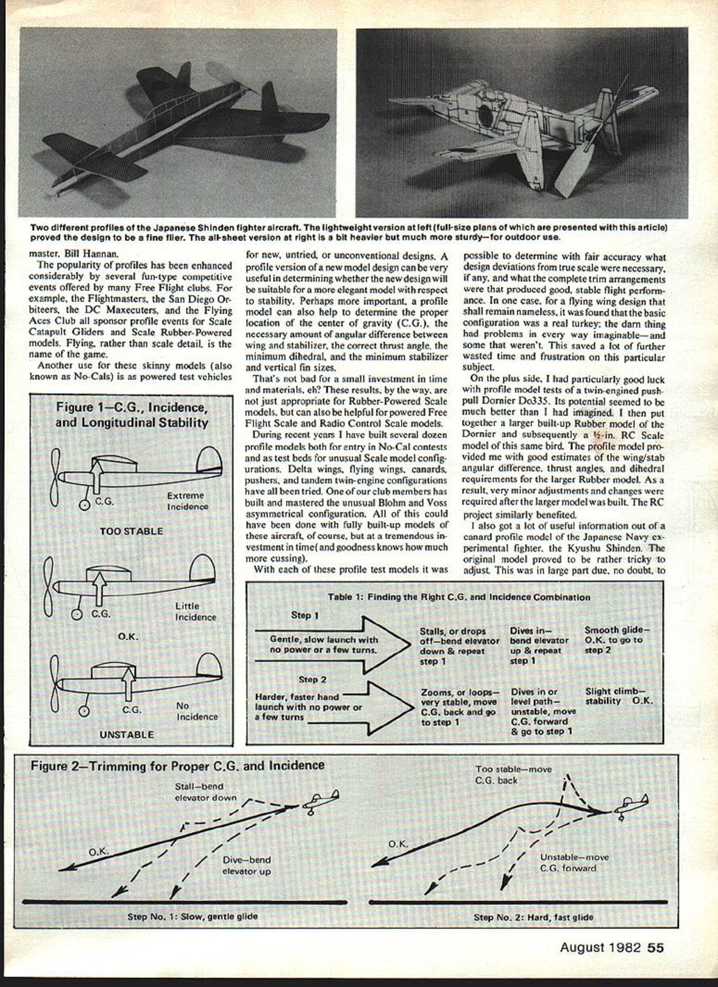
I also got a lot of useful information out of a canard profile model of the Japanese Navy experimental fighter, the Kyushu Shinden. The original model proved tricky to adjust — in large part because I had built and flown very few canards. Eventually the proper C.G. location was found, combined with what seemed to be an excessive amount of angular difference between the wing and forward canard surface. A fairly large amount of upthrust (the equivalent of downthrust in a tractor configuration) was also found necessary.
With these adjustments the Shinden demonstrated exceptional flight performance and stability, so a lighter profile model and a larger built-up rubber scale model were built using the same force arrangements as the original profile. The built-in adjustments worked exactly as on the profile, and only very minor trimming was required to get them both flying well.
Several other similar experiences have convinced me that these small profile models do provide accurate insight into the flight characteristics and trim requirements of a larger, built-up model. It's a simple and fun way to save time and frustration and to take most of the surprises out of trimming a large, new scale project. It can also steer you away from the real "dogs" that are not worth the effort.
For those who may not have trimmed many free flight scale models before, here are some procedures that have worked well. There are certainly many other ways to go about trimming a model, but these techniques are a good place to start and are very easy on a profile model.
C.G. and wing/stab angles
The idea is to determine the combination of C.G. and wing-to-tail angular difference that provides just enough pitch (up-and-down) stability. We don't want too much pitch stability, as this will add unnecessary drag; too little and the model won't fly. In general, the further forward the C.G., the greater the stability — and vice versa. We want the point at which pitch stability disappears or is marginal, then move the C.G. forward just a little until adequate stability reappears.
- Make sure all flying surfaces are straight and free of warps before testing. It's surprising how many modelers skip this step.
- Use modeling clay to place the C.G. at the point you think it should be or a little rearward of that. (Almost any place between the wing leading and trailing edges will do as a starter.) If in doubt, place the C.G. at one‑third the distance from the leading to the trailing edge. Mark the C.G. with a soft pencil to keep track.
- For the first tests, remove the propeller and replace it with a piece of modeling clay of equal weight if possible. The model glides better without the prop, making changes easier to observe. If the prop can't be removed, put a few turns in the rubber motor or let it free-wheel — we don't want thrust for these gliding tests.
First, gently glide the model (very few motor turns) and observe the flight path. During this phase only adjust the elevator until you get a smooth descending glide. Several glides with each trim setting will be necessary to be sure.
When the glide is reasonably smooth, repeat the glide with increasing speed (toss it harder than a normal launch). If the model tends to zoom upward sharply or loop, it is too stable. If it tends to tuck the nose under and dive at increased speeds, it is unstable. If the model continues in a shallow climb and then glides smoothly, it has a small margin of stability and you can proceed to power tests.
If the model zoomed upward or dove, move the C.G. about 1/8 in. by adding modeling clay to the nose or tail as follows:
- If it zoomed upward: move the C.G. rearward (clay on the tail) and bend the elevator trailing edge down a bit.
- If it dived: move the C.G. forward (clay in the nose) and bend the elevator trailing edge up a bit.
After making C.G. and incidence adjustments, return to gentle launches and adjust only the elevator to get a smooth glide. Repeat until you have found the C.G. and incidence combinations that are stable and unstable. The setting to use for powered tests will be just a little forward of the marginally stable point.
Figure 1 — C.G., Incidence, and Longitudinal Stability
- Too stable: C.G. far back — extreme incidence
- O.K.: C.G. proper — little incidence
- Unstable: C.G. forward — no incidence
Table 1 — Finding the Right C.G. and Incidence Combination Step 1
- Gentle, slow launch with no power or only a few turns:
- If it stalls or drops off — bend elevator down & repeat step 1.
- If it dives in — bend elevator up & repeat step 1.
- Smooth glide — O.K., go to step 2.
Step 2
- Harder, faster hand launch with no power or a few turns:
- Zooms or loops — very stable; move C.G. back and go to step 1.
- Dives in or levels — unstable; move C.G. forward & go to step 1.
- Slight climb — stability O.K.
Figure 2 — Trimming for Proper C.G. and Incidence Step 1: Slow, gentle glide
- Stall — bend elevator down
- Dive — bend elevator up
- O.K.
Step 2: Hard, fast glide
- Too stable — move C.G. back
- Unstable — move C.G. forward
- O.K.
Thrust line
Once the C.G. has been established in the glide tests, find the proper thrust-line angles. Put in a very small amount of rudder adjustment in the direction you want the flight path to be (or, on certain models, a clay weight on a wing tip works better than rudder trim). I usually use left turn for both power and glide.
Begin adding more turns as the power flight tests proceed, but this time use only thrust-angle changes to obtain a good power pattern. The adjustments are usually obvious:
- Point the thrust line downward to keep the model from zooming upward under the first burst of power.
- Point the thrust line opposite the direction of a turn that becomes too tight.
Use only very small thrust changes, a degree or two at a time, since the effect is large under full power.
Dihedral angle and tail area
If the model cannot be made to fly in a consistent circle in either direction without tightening its turn and eventually diving in, you probably have spiral stability problems. This is especially common in low-wing models with little dihedral, but it also appears in some parasol configurations with large vertical tail surfaces, such as the Curtiss Junior. The best remedy is usually to add more dihedral — about two or three degrees at a time — until the problem subsides.
Another possible solution is to reduce the vertical tail surface, but this usually looks bad and can lead to other stability problems.
One tricky method worth trying on certain models is to add vertical side area above the approximate C.G. position. Walt Mooney sometimes does this by filling in an open cabane structure with a clear sheet of thin plastic. You can hardly see it, and it will sometimes do the trick. On another of Walt's models he added a large profile pilot figure to the otherwise empty cockpit; this added enough lateral area above the C.G. for the low-wing model to fly properly with no dihedral at all.
Directional instability is another occasional problem. In this case the model will wander in direction and be impossible to adjust for a reliable turn pattern. Unlike spiral instability, the model will not tend to spin in; in fact, directional wandering usually means the model is spirally stable. The simple cure is to increase vertical tail area. If a large increase would spoil the looks, consider adding a transparent tab to the vertical tail; in flight it will hardly be visible.
If the model's flight path is erratic in pitch and difficult to get repeatable results while setting C.G. and incidence, the horizontal tail surfaces may be too small. Add 20 to 30% more horizontal tail area and try again.
Other peculiar trimming problems may arise from odd scale configurations; you can cut-and-try to solve them with your little profile test machine. The problems discussed above tend to be the most common for scale models.
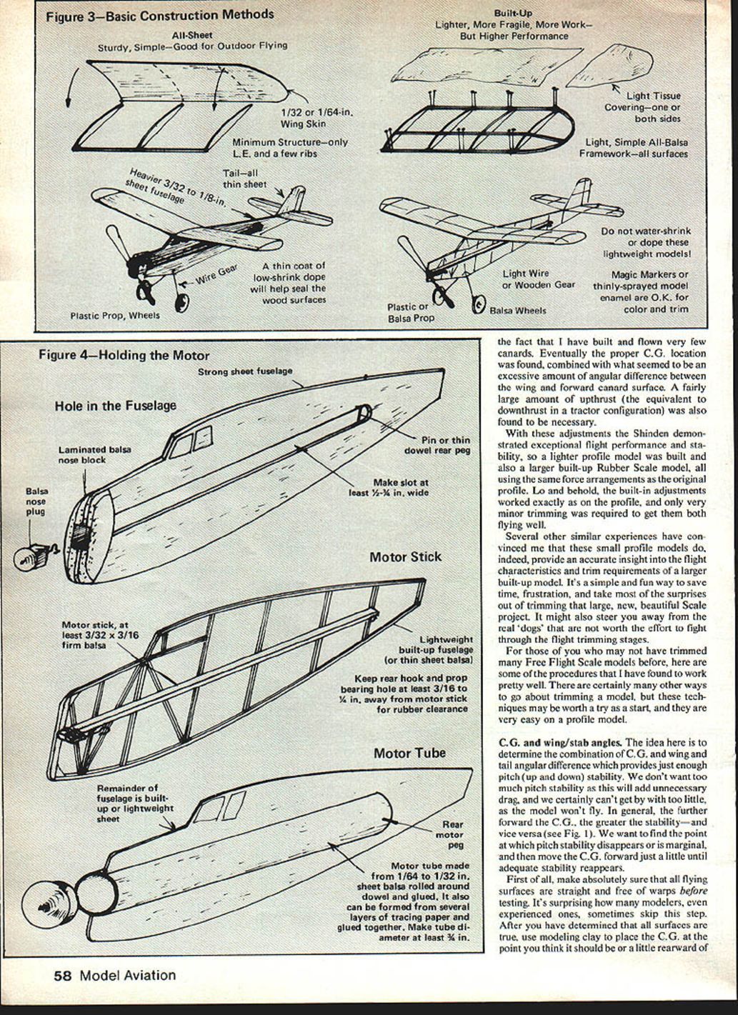
Construction methods
There are two basic structural approaches: all-sheet surfaces and built-up tissue-covered surfaces.
- Built-up, tissue-covered models:
- Can be built lighter than all-sheet models and therefore have potentially higher flight performance.
- Are usually used for indoor flying.
- Are a bit more time-consuming to build and tend to be somewhat more fragile.
- All-sheet models:
- Usually built from thin sheet balsa (1/16 to 1/64 in.).
- Some builders use thin sheet foam plastic of 1/32 to 3/32 in. thickness, sliced from dense foam blocks used for insulation.
- The foam is easy to use, lighter than balsa, less expensive, and virtually warp-proof.
- All-sheet profiles are simple to build, can be decorated with felt-tip pens, and are excellent beginner projects for powered free flight models.
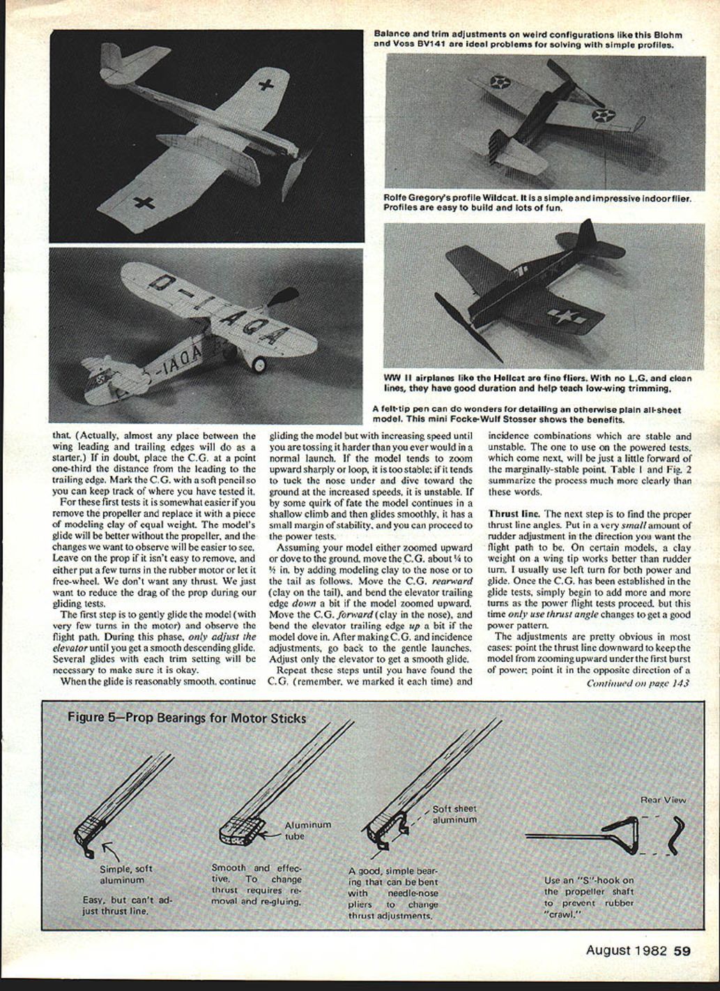
Holding the motor and prop
Three basic ways to support the rubber motor on the model:
- Hole in the fuselage — classic and most used; best for all-sheet balsa where the fuselage is rigid enough to support a fully wound motor.
- Motor stick — required if weaker construction is used (very thin sheet balsa, foam, or built-up structures). A motor stick can be a simple piece of 3/32 by 3/16 balsa or a small rolled tube of 1/32 or 1/64 balsa for very lightweight indoor models.
- Motor tube — fully enclose the rubber motor in a fairly large-diameter tube built as part of the fuselage. The tube should be at least 3/8 in. diameter to provide sufficient clearance for the unwinding rubber motor. Make the tube by wrapping 1/32 or 1/64 balsa, or several layers of paper, around a dowel.
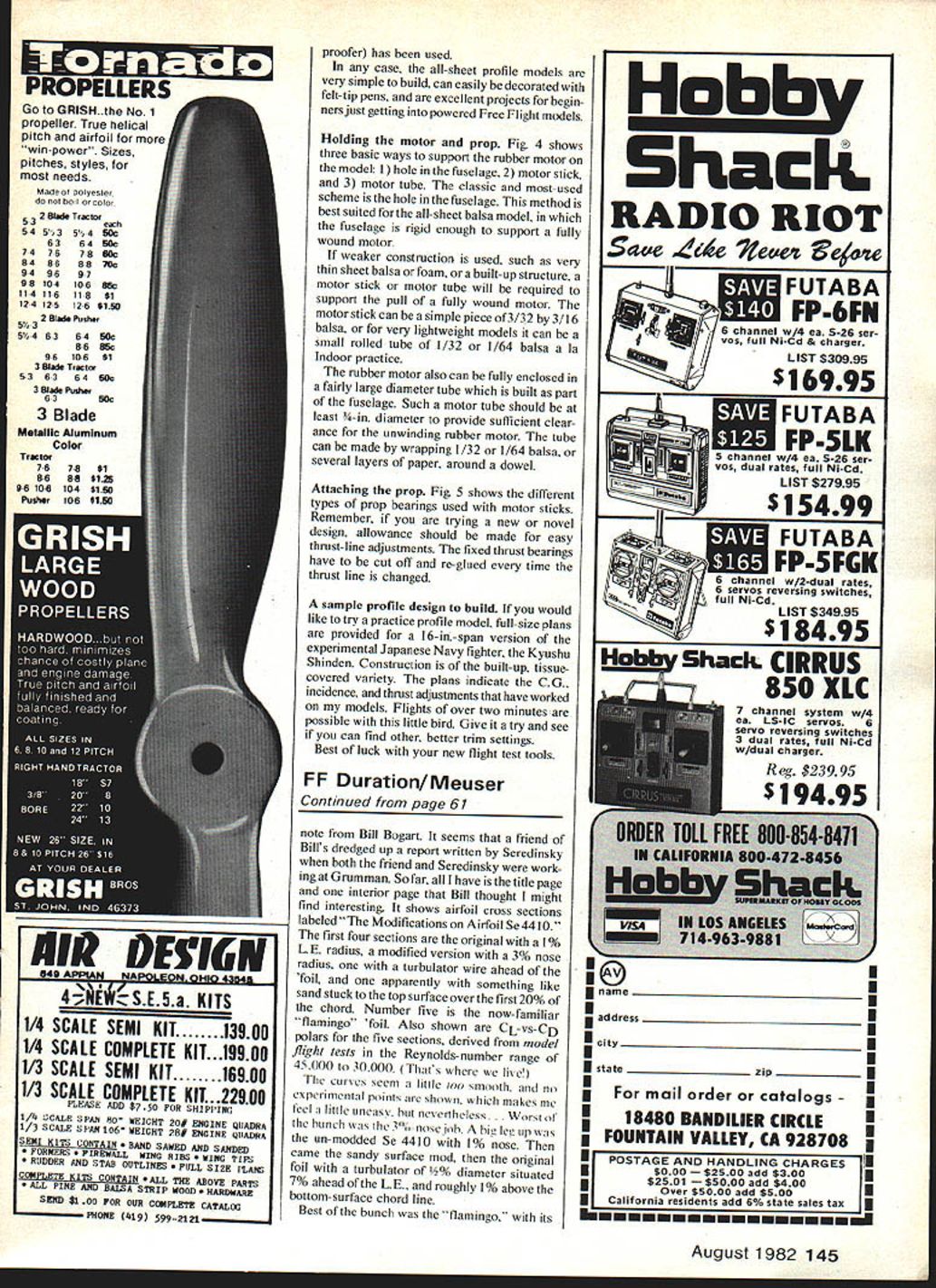
Attaching the prop
Different types of prop bearings are used with motor sticks. If you are trying a new or novel design, allow for easy thrust-line adjustments. Fixed thrust bearings have to be cut off and re-glued every time the thrust line is changed.
A sample profile design to build
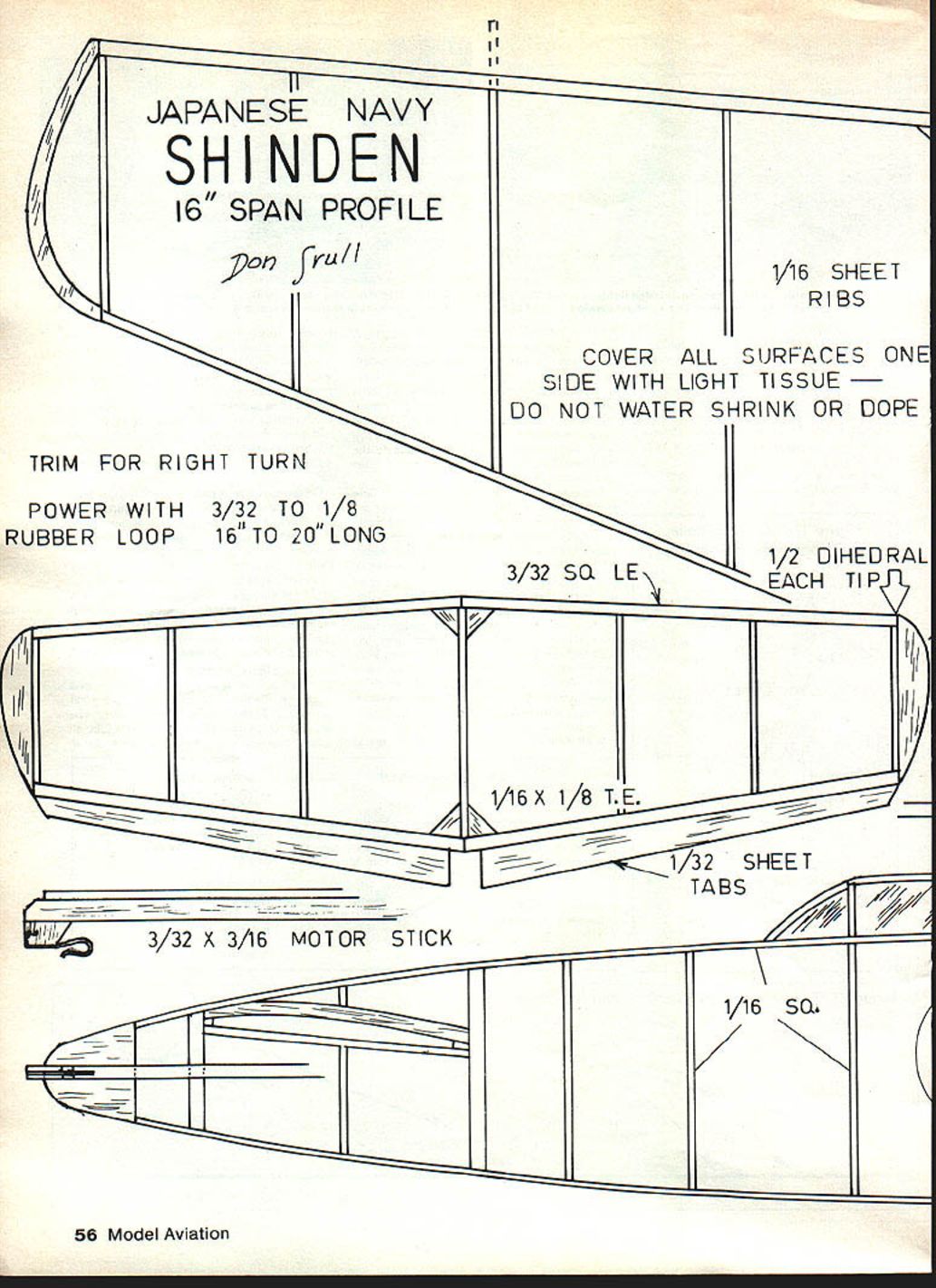
Full-size plans are provided for a 16-in.-span version of the experimental Japanese Navy fighter, the Kyushu Shinden. Construction is of the built-up, tissue-covered variety. The plans indicate the C.G., incidence, and thrust adjustments that have worked on my models. Flights of over two minutes are possible with this little bird. Give it a try and see if you can find other, better trim settings. Best of luck with your new flight test tools.
JAPANESE NAVY SHINDEN 16" SPAN PROFILE
Don Srull
- 1/16 sheet ribs
- Cover all surfaces one side with light tissue — do not water-shrink or dope
- Trim for right turn
- Power with 3/32 to 1/8 rubber loop, 16" to 20" long
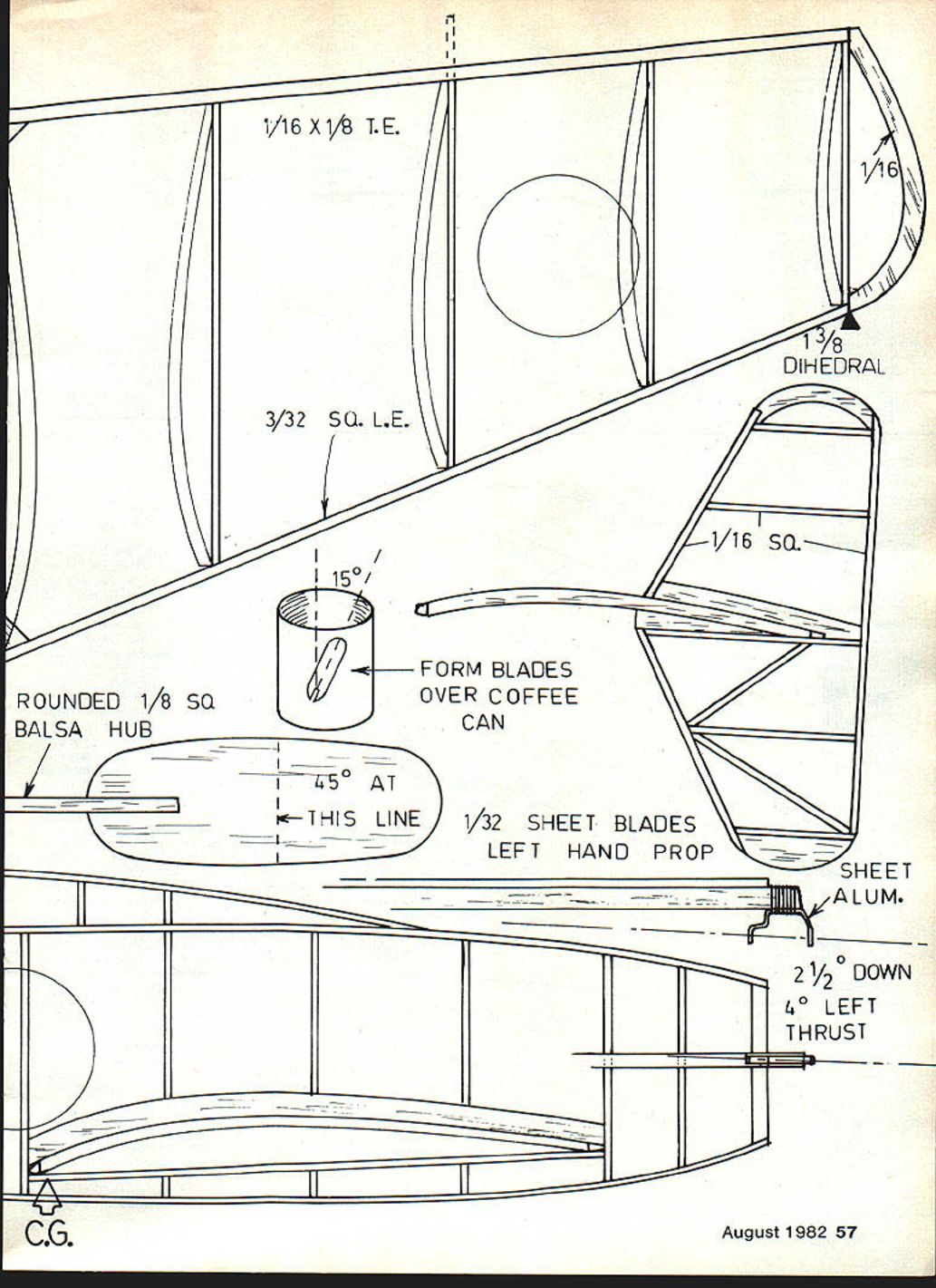
- 3/32 sq leading edge
- 1/2° dihedral each tip
- 1/16 x 1/8 trailing edge
- 1/32 sheet tabs
- 3/32 x 3/16 motor stick
- 1/16 sq
- Form blades over coffee can
- Rounded 1/8 sq balsa hub
- 45° at this line
- 1/32 sheet blades — left-hand prop
- Sheet aluminum (for spinner or reinforcement)
- 2 1/2° down thrust
- 4° left thrust
- C.G. (see plans)
- 1 3/8° dihedral overall
Flights exceeding two minutes are possible with proper trim. Use the trimming procedures above to refine C.G., incidence, thrust, and dihedral for best results.
Transcribed from original scans by AI. Minor OCR errors may remain.

