
Fuselage Jig for Copeland Racer
Stephen Kanyusik
The jig is up! The Copeland Racer's fuselage intimidated me until I designed this construction aid.
I believe everyone who has built a built-up fuselage has experienced the unfortunate result of the body twisting sideways after the stringers have been added. No matter how carefully they are applied, they often end up distorted. Rats! Gloriosky! and perhaps a razzle frazzle would be sounded. But of course, this frustration did not solve the problem.
I became interested in rubber-powered models through my recent association with the Cloudbusters Modeling Club (Detroit area). When I became brave enough to make the 1940 Copeland Wakefield Championship Model, I knew I would need some help. The dirigible-like fuselage had me intimidated! I first became aware of this model in the mid-1940s, and even though I admired it, it took 40 years for me to get up the courage to build it.
I found plans through Ron Moulton in England, and some pen pals sent articles from the December 1946 issue of Aeromodeller. So I designed a fuselage jig, and it was very successful in achieving the desired shape.
Jig overview
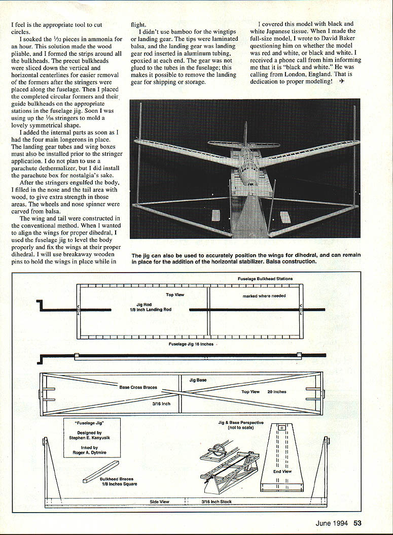
The jig is composed of three parts:
- The base
- The fuselage jig (the main form)
- The bulkhead braces
The base
- Material: 3/16-inch balsa (I used a bundle of 3/16 x 3 x 36-inch stock).
- Dimensions: 20 inches long and 3 inches wide.
- The end supports that hold the jig are 5 inches high.
- A landing gear rod is used with the jig for alignment of the bulkheads.
I feel the base should be a couple of inches longer than the jig, and the height should let the jig rotate and clear for convenience when working on the various fuselage parts.
The fuselage jig
- Material: 1/8-inch square balsa.
- Size: 4 inches wide and 16 inches long (the size can be customized to suit the builder's needs).
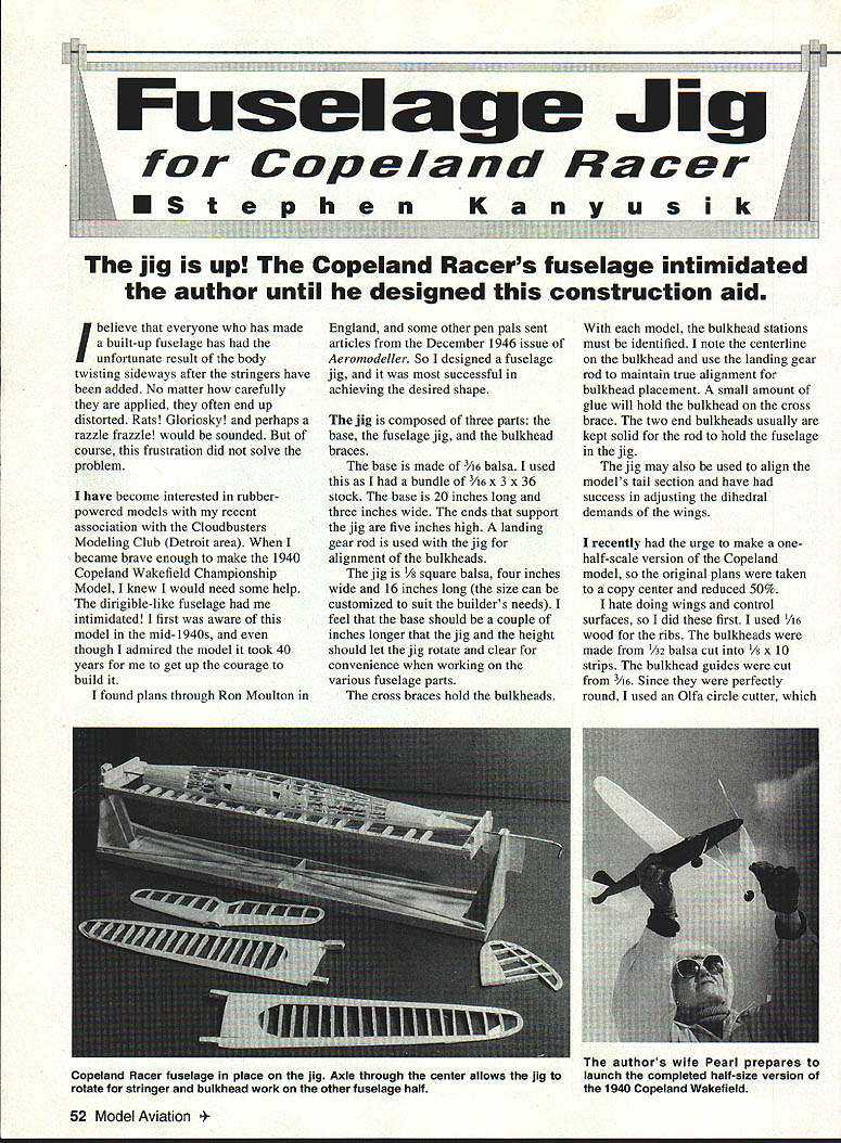
The cross braces hold the bulkheads. With each model, the bulkhead stations must be identified. I mark the centerline on each bulkhead and use the landing gear rod to maintain true alignment for bulkhead placement. A small amount of glue will hold a bulkhead on the cross brace. The two end bulkheads are usually kept solid so the rod can hold the fuselage in the jig.
The jig may also be used to align the model's tail section, and I have had success in adjusting the dihedral requirements of the wings.
Building a half-scale version
I recently had the urge to make a one-half-scale version of the Copeland model, so I took the original plans to a copy center and reduced them to 50%.
I dislike doing wings and control surfaces, so I built those first. I used 1/16-inch wood for the ribs. The bulkheads were made from 1/32-inch balsa cut into 1/8-inch by 10-inch strips. The bulkhead guides were cut from 3/16-inch stock. Since the guides were perfectly round, I used an Olfa circle cutter, which I feel is the appropriate tool to cut circles.
I soaked the 1/32-inch strips in ammonia for an hour. This solution made the wood pliable, and I formed the strips around all of the bulkheads. The precut bulkheads were sliced down the vertical and horizontal centerlines for easier removal of the formers after the stringers were placed along the fuselage.
Then I placed the completed circular formers and their guide bulkheads on the appropriate stations in the fuselage jig. Soon I was using up the 1/16-inch stringers to mold a lovely symmetrical shape.
Assembly and internal structure
I added the internal parts as soon as I had the four main longerons in place. The landing gear tubes and wing boxes must also be installed prior to the stringer application. I did not plan to use a parachute dethermalizer, but I installed the parachute box for nostalgia's sake.
After the stringers encased the body, I filled in the nose and tail area with wood to give extra strength in those areas. The wheels and nose spinner were carved from balsa.
Wings, tail, and gear
The wing and tail were constructed by conventional methods. When I wanted to align the wings for proper dihedral, I used the fuselage jig to level the body and fix the wings at their proper dihedral. I will use breakaway wooden pins to hold the wings in place while in flight.
I didn't use bamboo for the wingtips or landing gear. The tips were laminated balsa, and the landing gear was a landing gear rod inserted in aluminum tubing, epoxied at each end. The gear was not glued to the tubes in the fuselage; this makes it possible to remove the landing gear for shipping or storage.
Covering and finishing
I covered this model with black and white Japanese tissue. When I made the full-size model, I wrote to David Baker questioning whether the model was red and white, or black and white. He phoned to inform me that it is "black and white." He was calling from London, England. That is dedication to proper modeling!
Transcribed from original scans by AI. Minor OCR errors may remain.

