

FW-190 A-3 Wurger
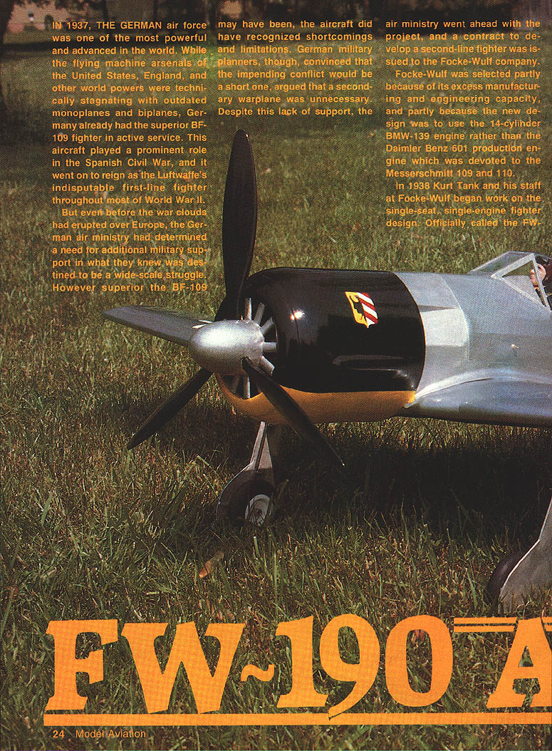
In 1937 the German air force was one of the most powerful and advanced in the world. While the flying-machine arsenals of the United States, England, and other world powers were technically stagnating with outdated monoplanes and biplanes, Germany already had the superior Bf 109 fighter in active service. This aircraft played a prominent role in the Spanish Civil War and went on to reign as the Luftwaffe's indisputable first-line fighter throughout most of World War II.
Even before war clouds erupted over Europe, the German air ministry had determined a need for additional military support in what they expected to be a wide-scale struggle. However superior the Bf 109 may have been, that aircraft had recognized shortcomings and limitations. German military planners, convinced the impending conflict would be short, argued that a secondary warplane was unnecessary. Despite this lack of support, the air ministry issued a contract to Focke-Wulf to develop a second-line fighter.
Focke-Wulf was selected partly because of its excess manufacturing and engineering capacity, and partly because the new design was to use the 14-cylinder BMW-139 air-cooled radial engine rather than the Daimler-Benz DB 601 production engine that was devoted to the Messerschmitt Bf 109 and Bf 110.
In 1938 Kurt Tank and his staff at Focke-Wulf began work on the single-seat, single-engine fighter design. Officially called the Fw 190, it was designed around the twin-row, 14-cylinder BMW-139 air-cooled radial engine. The first prototype, the Fw 190 V1, used a large ducted spinner the same diameter as the cowling; this system failed to provide adequate cooling and the V1 began overheating. Problems such as this plagued early Focke-Wulfs until better ducting and cooling arrangements were developed.
Although the Bf 109 remained Germany's principal fighter throughout World War II, the Fw 190 became an important component of the Luftwaffe's tactical, multirole attack force. Over the course of the war the Würger (Wurger) was equipped with a wide range of armament and stores:
- 7.92-mm MG-17 machine guns
- 20-mm and 30-mm cannons
- 1,000-lb bombs
Recognizing and exploiting the aircraft's versatility, the Luftwaffe deployed it as:
- fighter
- fighter-bomber
- torpedo bomber
- reconnaissance plane
- ground-support aircraft
- all-weather and night fighter
Wingspan: 34 ft 5 in; takeoff weight: 8,000 lb. The Würger was lighter and smaller than many Allied fighters. For comparison:
- P-47D: wingspan 40 ft 9 in; takeoff weight 13,500 lb
- P-51D: wingspan 37 ft; takeoff weight 10,000 lb
Interest in the Würger has extended to museum restoration facilities such as the Smithsonian's Silver Hill, MD, restoration shop, where an FW-190 has been part of collection and restoration activities.
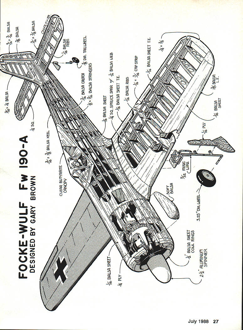
FOCKE-WULF Fw 190-A
Designed by Gary Brown
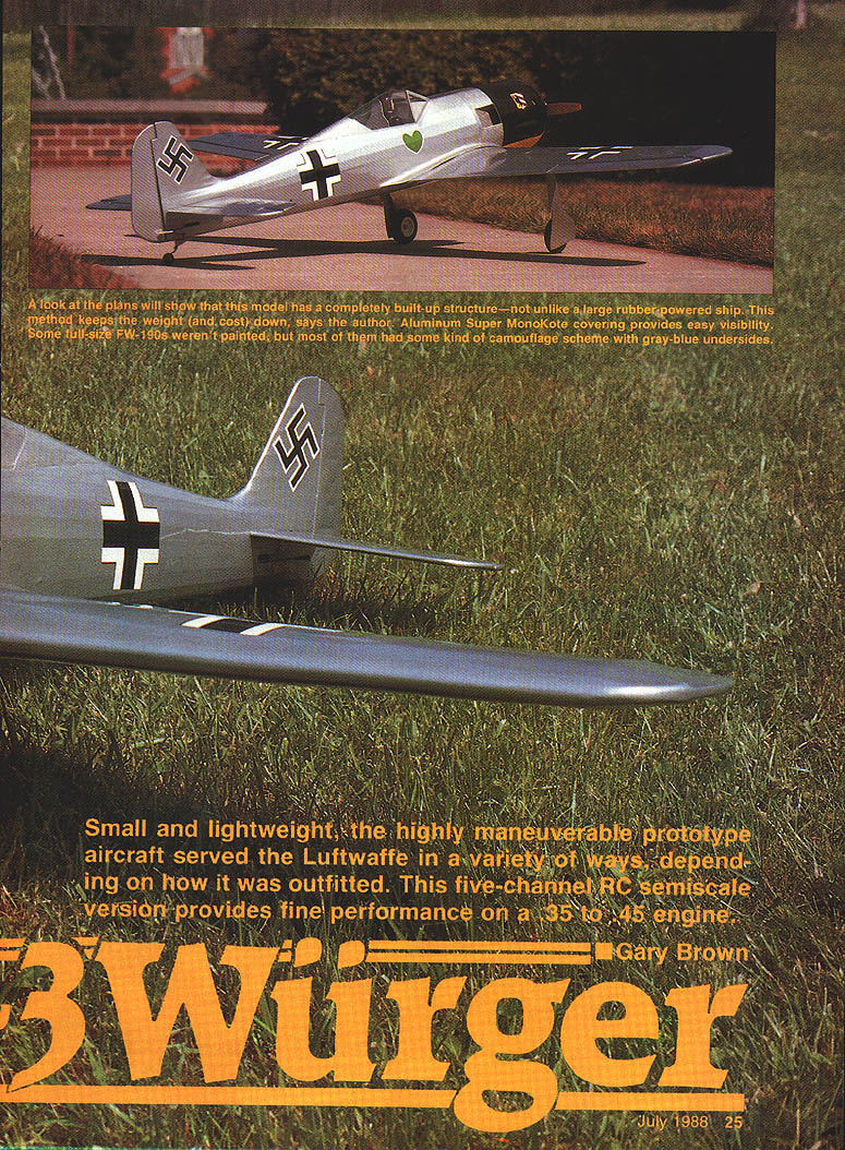
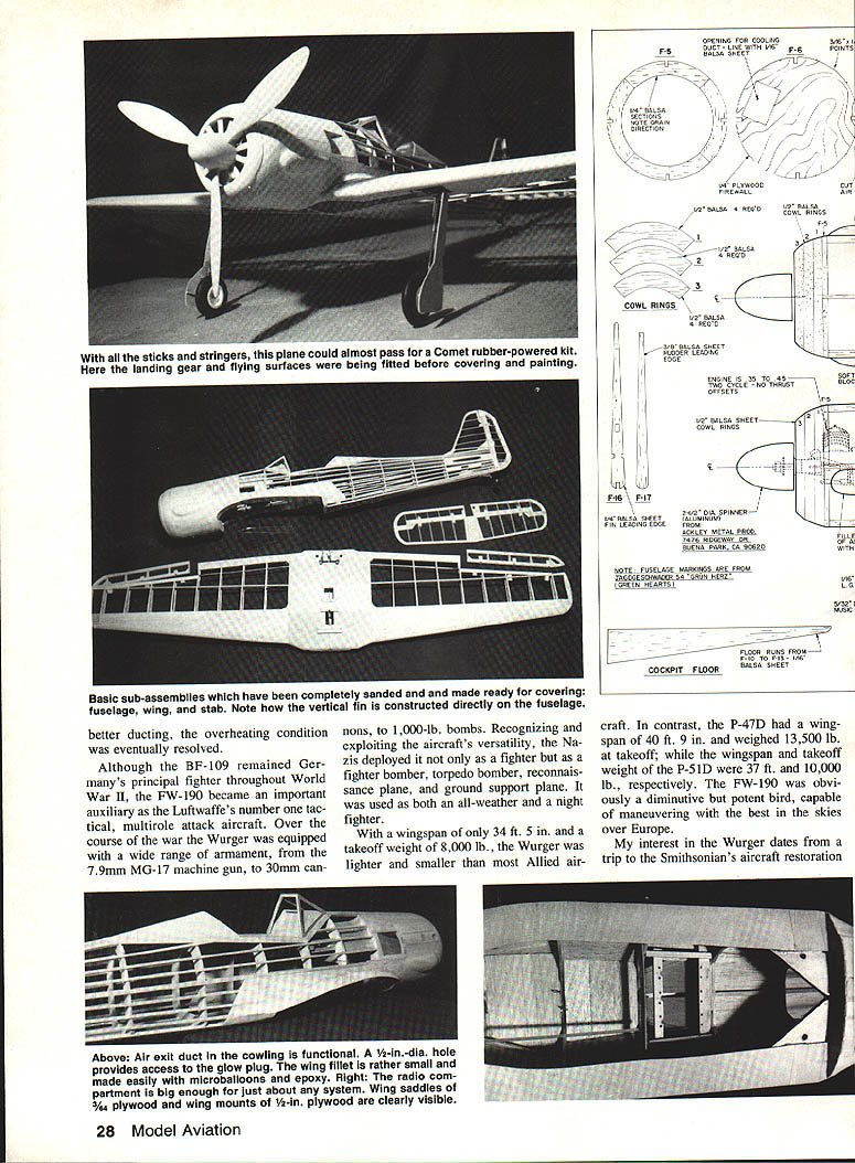
No primary article text appears on this scanned page beyond the photographs, captions, and plan/parts notes. The following is material collected from study and restoration that served as the basis for an RC semiscale model project. The intent was not an exact scale replica for competition but a lightweight semiscale design with retracts capable of good performance on a .35 or .40 engine.
I visited restoration facilities where several planes were undergoing work (a Japanese Nakajima Irving twin and night fighter, an early Northrop flying wing, and an Fw 190). Fascinated by the compact size of the Focke-Wulf design, I studied the aircraft closely and began collecting material to recreate it as an RC model. The completed model described here weighs about 5 lb and has been flown on an old K&B .35 and later an HP .40 for improved performance. It carries the Jagdgeschwader 54 "Grünherz" insignia: the green heart was the Geschwader emblem and the cowl shield was the Gruppen insignia.
If you've built an Old-Timer or stick-type model, constructing the Würger should present no unwelcome surprises. Before you begin, however, study the plans and thoroughly acquaint yourself with the design.
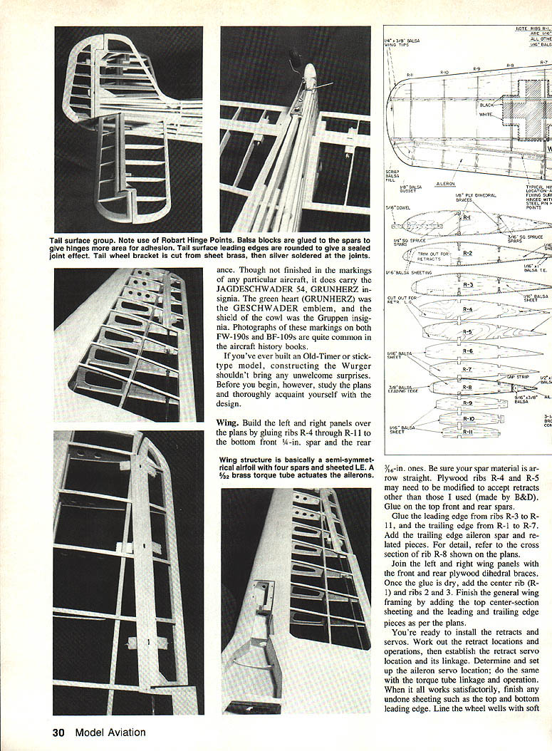
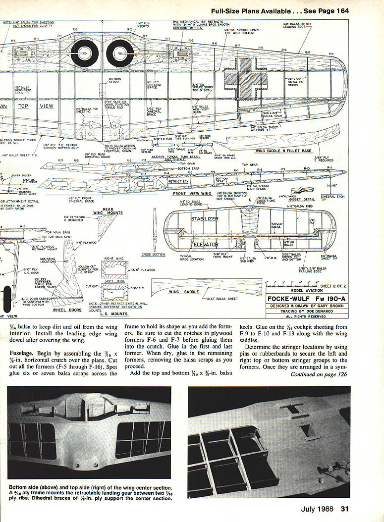
Wing
- Build left and right panels over the plans by gluing ribs R-4 through R-11 to the bottom front 1/4-in. spar and the rear 3/16-in. spar. Ensure spar material is arrow-straight.
- Plywood ribs R-4 and R-5 may need modification to accept retracts other than the B&D retracts used here.
- Glue on the top front and rear spars.
- Glue the leading edge from ribs R-3 to R-11 and the trailing edge from R-1 to R-7. Add the trailing-edge aileron spar and related pieces. Refer to the cross section of rib R-8 on the plans for detail.
- Join left and right wing panels with the front and rear plywood dihedral braces. Once dry, add center rib (R-1) and ribs 2 and 3.
- Finish general wing framing by adding top center-section sheeting and the leading and trailing edge pieces per the plans.
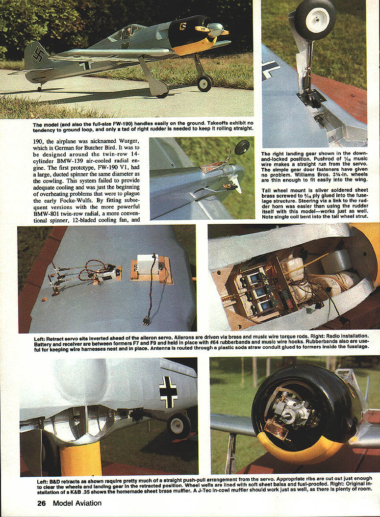
- Install retracts and servos after determining locations and linkages. Establish retract servo location and linkage, aileron servo location, and torque-tube linkage until all operations work satisfactorily.
- Finish any undone sheeting such as top and bottom leading edge. Line wheel wells with soft 1/16-in. balsa to keep dirt and oil from the wing interior.
- Install the leading-edge wing dowel after covering the wing.
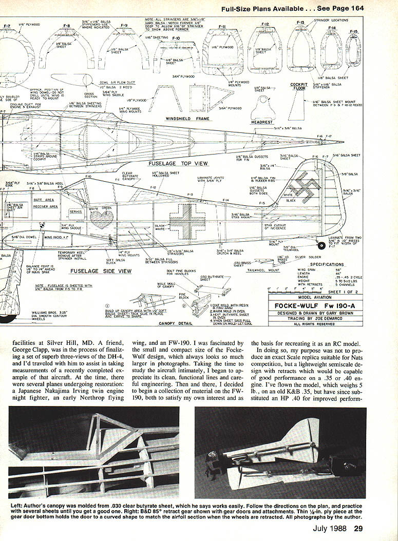
Fuselage
- Assemble the 3/8 x 3/8-in. horizontal crutch over the plans. Cut out formers F-5 through F-16.
- Spot-glue six or seven balsa scraps across the frame to hold shape while adding formers. Cut the notches in plywood formers F-6 and F-7 before gluing them into the crutch.
- Glue in the first and last former; when dry, glue in the remaining formers and remove the balsa scraps as you proceed.
- Add top and bottom 1/16 x 3/8-in. balsa keels. Glue on 1/16 cockpit sheeting from F-9 to F-10 and F-13 along with the wing saddles.
- Determine stringer locations by using pins or rubber bands to secure left and right top or bottom stringer groups to the formers. Once symmetrical, glue on the stringers.
- Add the cowling rings and forward fuselage sheeting. Include the cooling duct in the scale location on the right side of the fuselage — it vents hot air from the cowl and provides an outlet for muffler exhaust.
- The rear wing bolt mounts are 1/4-in. plywood, drilled and threaded to fit standard 1/4-in. nylon wing bolts; epoxy them to the wing saddles and former F-11.
- Build the stabilizer, fin, and rudder over the plans, cover, and glue or hinge in place. The fin is constructed directly on the fuselage after former F-16 is attached.
Finishing, covering, and hardware
- Before covering, trial-fit hardware: engine, tank, radio, servos, landing gear, movable surfaces, etc. Confirm fit before covering.
- Form the canopy by stretching heated .030 butyrate over a male mold of the canopy. Practice with several sheets before final forming.
- Use Robart hinge points for all hinges — they provide a scalelike hinge joint and good effectiveness.
- Fuel-proof usual areas before covering: cowling interior (engine compartment), rear of firewall (fuel tank area), and engine cooling duct. Thinned epoxy glue or polyester dope work well.
Hinges and control throws
- Recommended initial control surface movements:
- Ailerons: 3/8 in. up, 1/16 in. down
- Elevator: 3/8 in. up, 5/16 in. down
- Rudder: 3/8 in. left and right
- If you balance at the point shown on the plans, add 1/2 in. up trim to the elevator for initial flights in addition to the above movements.
Engine and muffler
- Mount the engine to a Kraft-type mount, attach the muffler, then bolt the assembly to the firewall with 4-40 bolts and blind nuts. The engine mount will fit through the front cowl, so a removable hatch is unnecessary.
- The builder fabricated an in-cowl muffler from sheet brass silver-soldered together. Commercial J-Tec in-cowl mufflers should also work well; there is plenty of room inside the cowling.
Landing gear options
- If you prefer not to install retracts, standard fixed wire gear and grooved wood blocks can be substituted; mount the blocks into 1/8-in. plywood ribs.
- The plans used B&D mechanical retracts with a Futaba FPS-9 retract servo — a reliable combination.
- Smooth contour wheels of 3/4-in. diameter from Williams Bros. are narrow enough to fit inside the wing with proper landing-gear angle.
Weight and structural advice
- Target ready-to-fly weight: about 5 lb. Avoid overbuilding; excess structure adds weight and degrades performance.
Setup and flying
- With weight kept down, the Fw 190 model flies well with no bad habits. Takeoffs are straight with minimal ground-loop tendency and only modest right-rudder correction required. Wide-spaced mains contribute to good ground manners.
- The model will rise off ground (ROG) when at flying speed without elevator input. A little elevator and a healthy .40 give a good climbout.
- Landings are manageable: drop the gear and practice approaches, gradually slowing to landing speed. Use the rudder to keep it straight; the model slows nicely without threatening to stall.
- Propeller experimentation:
- A 10 x 6 works conventionally with a .40 engine.
- A 12 x 4 Zinger gives the best climb/pull.
- An 11 x 6 seems better for speed.
- Moral: experiment with diameters and pitches for best performance.
With clean lines and easygoing flying disposition, the Fw 190 makes a good choice for a workbench project. It is not overly demanding to build and is very satisfying at the flying field.
Transcribed from original scans by AI. Minor OCR errors may remain.

