
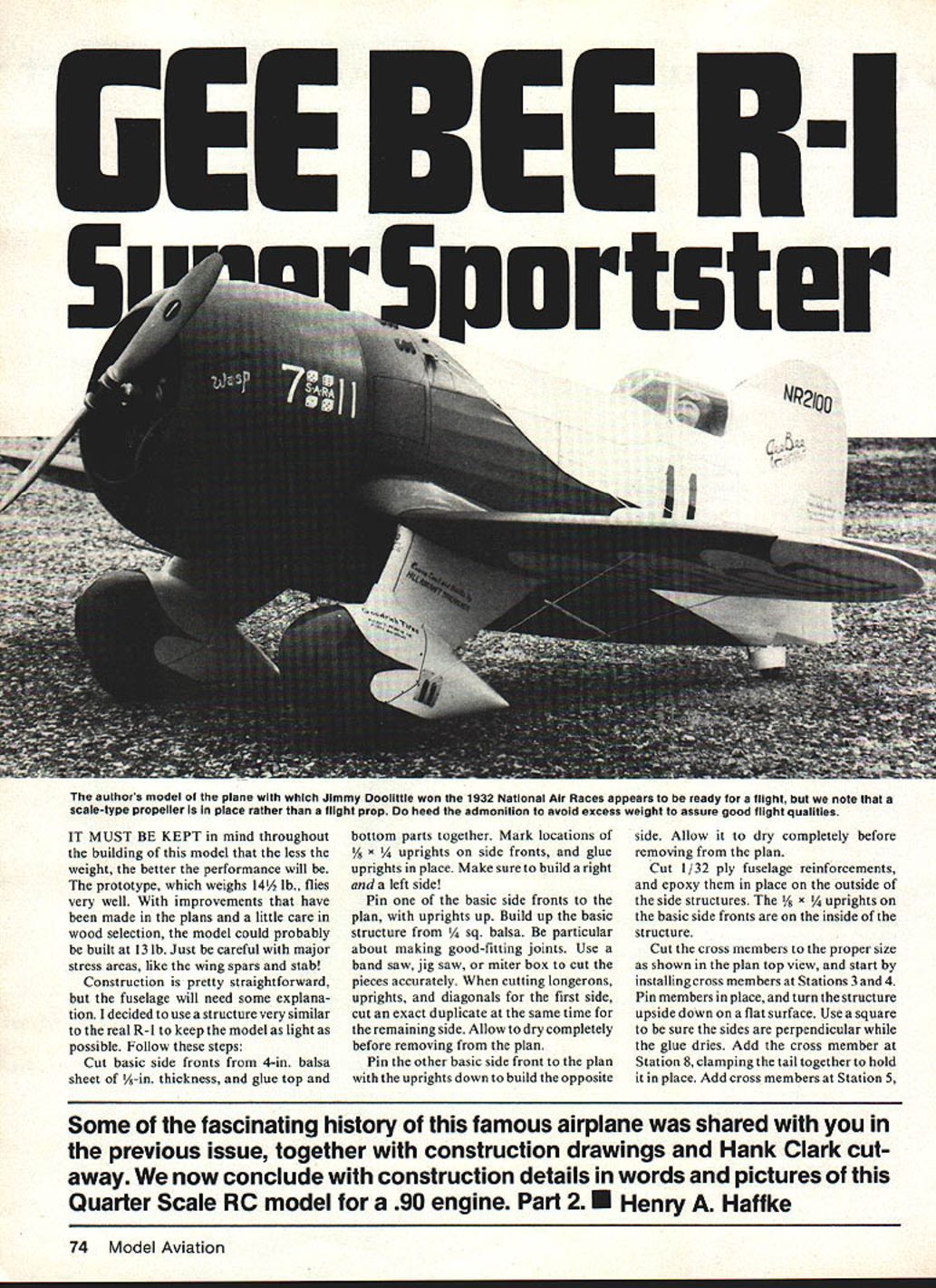
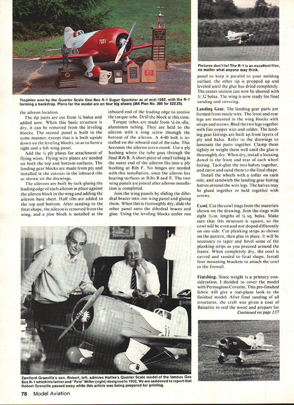
GEE BEE R-1 Super Sportster
It must be kept in mind throughout the building of this model that the less the weight, the better the performance will be. The prototype, which weighs 14 1/2 lb., flies very well. With improvements made in the plans and a little care in wood selection, the model could probably be built at 13 lb. Just be careful with major stress areas, like the wing spars and stabilizer.
Construction is straightforward overall, but the fuselage requires careful work. A structure very similar to the real R-1 was used to keep the model as light as possible. Follow these steps:
Fuselage
- Prepare the basic side fronts
- Cut basic side fronts from 4-in. balsa sheet of 1/8-in. thickness, and glue top and bottom parts together.
- Mark locations of 1/8 x 1/4 uprights on the side fronts, and glue uprights in place. Make sure to build a right and a left side!
- Build the first side
- Pin one of the basic side fronts to the plan, with uprights up.
- Build up the basic structure from 1/4 sq. balsa. Be particular about making good-fitting joints. Use a band saw, jig saw, or miter box to cut the pieces accurately.
- When cutting longerons, uprights, and diagonals for the first side, cut an exact duplicate at the same time for the remaining side.
- Allow to dry completely before removing from the plan.
- Build the opposite side
- Pin the other basic side front to the plan with the uprights down to build the opposite side.
- Allow it to dry completely before removing from the plan.
- Reinforce side structures
- Cut 1/32 ply fuselage reinforcements and epoxy them in place on the outside of the side structures. (The 1/8 x 1/4 uprights on the basic side fronts are on the inside of the structure.)
- Cut gussets from scrap balsa and install them at all cross-member joints, top and bottom, as shown in the bottom fuselage view.
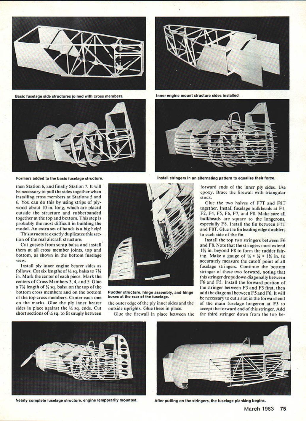
- Install cross members and assemble the box
- Cut the cross members to the proper size as shown in the plan top view.
- Start by installing cross members at Stations 3 and 4. Pin members in place, and turn the structure upside down on a flat surface. Use a square to be sure the sides are perpendicular while the glue dries.
- Add the cross member at Station 8, clamping the tail together to hold it in place.
- Add cross members at Stations 5 and 6. Install Station 7 last to pull the sides together.
- Installing cross members at Stations 5 and 6 can be done using strips of plywood about 10 in. long placed outside the structure and rubber-banded together top and bottom. This step is probably the most difficult in building the model; an extra set of hands is a big help.
- This structure exactly duplicates this section of the real aircraft.
- Install ply inner engine bearer sides
- Cut six lengths of 1/4 sq. balsa to 7-3/4 in. Mark the center of each piece.
- Mark the centers of Cross Members 3, 4, and 5.
- Glue a 7-3/4 in. length of 1/4 sq. balsa on the top of the bottom cross members and on the bottom of the top cross members. Center each one on the marks.
- Glue the ply inner bearer sides in place against the 1/4 sq. ends.
- Cut short sections of 1/4 sq. to fit snugly between the outer edge of the ply inner sides and the outside uprights. Glue these in place.
- Glue the firewall in place between the forward ends of the inner ply sides using epoxy. Brace the firewall with triangular stock.
- Install bulkheads and fin
- Glue the two halves of F7T and F8T together.
- Install fuselage bulkheads at F1, F2, F4, F5, F6, F7, and F8. Make sure all bulkheads are square to the longerons, especially F8.
- Install the fin between F7T and F8T. Glue the fin leading edge doublers to each side of the fin.
- Install stringers
- Install the top two stringers between F6 and F8. Note that the stringers must extend 1-1/8 in. beyond F8 to form the rudder fairing.
- Make a gauge of 5/8 x 1/4 x 1-5/8 in. to accurately measure the cutoff point of all fuselage stringers.
- Continue the bottom stringer of these two forward, noting that this stringer drops down diagonally between F6 and F5. Install the forward portion of the stringer between F3 and F5 first, then add the diagonal between F5 and F6. It will be necessary to cut a slot in the forward end of the main fuselage longeron at F3 to accept the forward end of this stringer.
- Add the third stringer down from the top between F5 and F8. The front stringer butts against F5 just below the diagonal.
- Install side stringers alternately side to side; side stringers must extend to the end.
- An extra stringer is added between the bottom stringers and the side stringers on each side. Cutouts for this stringer must be made, and it will be necessary to taper down the ends of this stringer where it joins the fuselage longeron at F5 and F8.
- Install stringers in an alternating pattern to equalize force on the structure.
- Install tailwheel mount and formers
- Install a 1/8 ply tail wheel mount plate and hardwood tail wheel mount block. Epoxy parts in place.
- Drill the block for the tail wheel wire. Cut a groove in the block and a hole in the rear block; epoxy the tail wheel wire in the groove.
- Install former F5A. The bottom diagonal lines up with the wing saddle cutout and touches F5B low point.
- Fuselage planking and sheeting
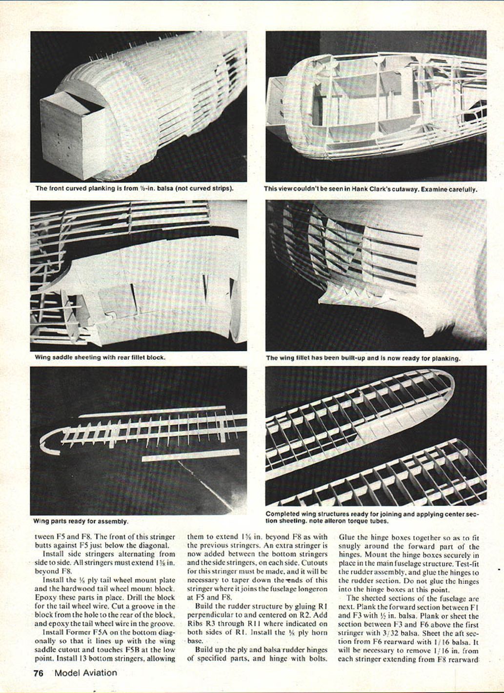
- After putting on the stringers, begin fuselage planking between F5 and F8.
- Plank the forward section between F1 and F3 with 1/8 in. balsa.
- Plank or sheet the section between F3 and F6 above the first stringer with 3/32 in. balsa.
- Sheet the aft section from F6 rearward with 1/16 in. balsa. It will be necessary to remove 1/16 in. from each stringer extending from F8 rearward to accept the sheeting.
- Glue 1/16 in. filler strips in the lower wing saddle and sand the saddle to match the wing fillet.
- Prepare and install sheeting for the rudder fairing.
Rudder
- Build the rudder structure by gluing R1 perpendicular to and centered on R2.
- Add ribs R3 through R11 where indicated on both sides of R1.
- Install the 1/8 ply horn base.
- Build up the ply and balsa rudder structure of the specified parts, and hinge with bolts.
- Glue the hinge boxes together so they fit snugly around the forward part of the hinges. Mount the hinge boxes securely in place in the main fuselage structure.
- Test-fit the rudder assembly and glue the hinges to the rudder section. Do not glue the hinges into the hinge boxes at this point.
Stabilizer and Elevator
- The stabilizer is made from 1/4-in. hard balsa sheet. Cut it to shape and sand the edges round.
- The elevator halves are built from a 3/32-in. balsa base with a 1/2 x 1/4 hardwood spar at the leading edge.
- Add ribs of 3/32 sq. balsa top and bottom, and sand them to a taper at the trailing edge.
- Join the elevator halves using a commercially available horn (such as those made by Sig).
Wing
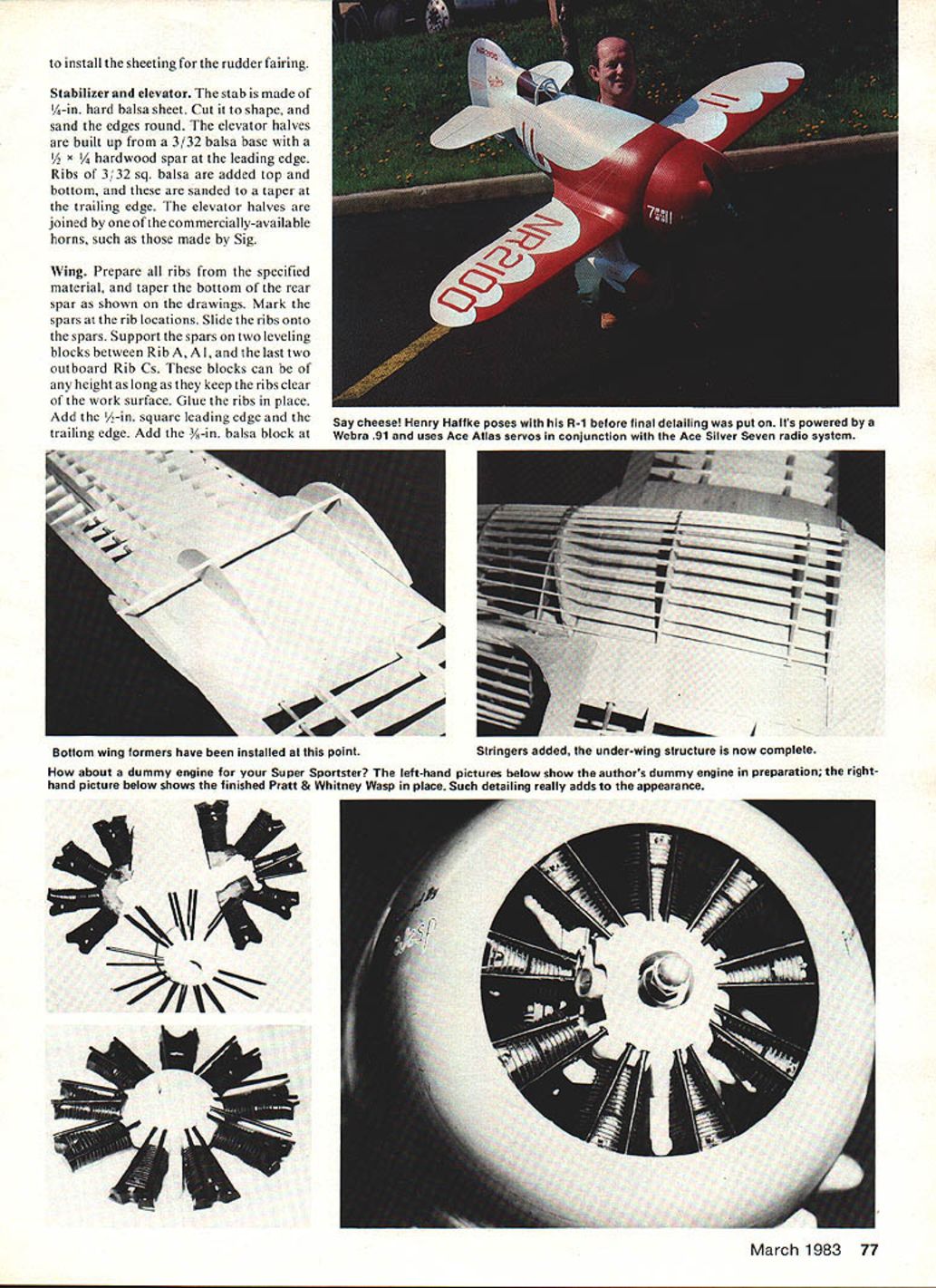
- Ribs and spars
- Prepare all ribs from the specified material, and taper the bottom of the rear spar as shown on the drawings.
- Mark the spars at the rib locations and slide the ribs onto the spars.
- Support the spars on two leveling blocks between Rib A, A1, and the last two outboard Rib Cs. These blocks can be of any height as long as they keep the ribs clear of the work surface.
- Glue the ribs in place.
- Leading edge, trailing edge, and aileron preparations
- Add the 1/2-in. square leading edge and the trailing edge.
- Add the 3/8-in. balsa block at the aileron location.
- Cut tip parts from 1/4-in. balsa and add them now.
- When the basic structure is dry, remove it from the leveling blocks.
- Build the second panel in the same manner, but upside down on the leveling blocks to produce right and left panels.
- Fittings and landing gear blocks
- Add 1/8 ply plates for attachment of flying wires on both the top and bottom surfaces.
- Fabricate landing gear blocks from ply and install them in the cutouts in the inboard ribs as shown on the drawings.
- Ailerons and torque tubes
- Build the ailerons by tack-gluing the leading edge of each aileron against the aileron block in the wing and adding the aileron base sheet.
- Add half ribs to the top and bottom. After sanding to the final shape, remove the aileron from the wing and install a pine block at the inboard end of the leading edge to receive the torque tube. Drill the block.
- Torque tubes are made from 1/4-in.-dia. aluminum tubing. Hold the tube to the aileron with a long screw through the bottom of the aileron. Install a 4-40 bolt on the inboard end of the tube to serve as the aileron servo crank.
- Use a ply bushing where the tube goes through the final Rib B. A short piece of small tubing in the outer end of the aileron fits into a ply bushing at Rib F. No hinges are needed with this installation, since the aileron has bearing surfaces at Ribs B and F.
- Join panels and center section
- Join the wing panels by sliding the dihedral braces into one wing panel and gluing them. When dry, slide the other panel onto the dihedral braces and glue.
- With one panel supported on leveling blocks, prop the other tip up and level until the glue dries.
- Sheet the center section with 3/32-in. balsa.
- Final sand and cover the wing.
Landing Gear
- Form landing gear parts from music wire. The front and rear legs are mounted in the wing blocks with straps and screws.
- Bind the two legs together with fine copper wire and solder.
- Build landing gear fairings from layers of ply and balsa. Refer to the drawings to laminate the parts together. Clamp tightly or weight them until dry.
- When dry, install a locating dowel in the front and rear of each wheel fairing. Tack-glue the two halves together, carve, and sand to final shape.
- Install the wheels with a collar on each side, and sandwich the landing gear fairing halves around the wire legs. The halves may be glued together or held with screws.
Cowl
- Cut the cowl rings from the materials shown on the drawing.
- Join the rings with eight 1/2-in. lengths of 1/4 sq. balsa. Make sure the structure is square so the cowl sits true.
- Cut planking strips as shown on the pattern and glue in place. Taper and bevel some strips as you proceed around the frame.
- When completely dry, carve and sand the cowl to final shape.
- Install four mounting brackets to attach the cowl to the firewall.
Finishing
- Since weight is a primary consideration, cover the model with Permagloss Coverite pre-finished fabric for a real-plane look.
- After final sanding of all structures, seal the wood with a coat of Balsarite to prepare for covering.
- Apply white Permagloss to the entire airframe. Cut red trim from bright red Permagloss using patterns made from the plans and iron over the white. Use black pinstriping tape to separate colors.
- Cut registration and racing numbers from Coverite Graphics material and apply. Outline numbers with black pinstriping.
- Keep detailing to a minimum to save weight. Use lightweight hardware where possible. Carve the headrest and oil cooler from balsa, as well as the under-cowl scoop and lower access panels.
- Make cockpit seats from sheet balsa and cover with cloth for realism. Paint and install a simple instrument panel.
- Build wheel pants over a balsa plug, hollow and finish after covering.
- Laminate cowl assemblies from balsa rings, carve to shape, and fit to the firewall with light plywood doublers and small screws.
- Fabricate exhaust stacks from brass tubing and solder in place.
Flight Notes and Conclusion
- In flight the model is very fast and responsive. With the .90 engine it will reach speeds where smooth flying and conservative control throws are recommended until you become familiar with its speed.
- Takeoffs and landings require a smooth flare but are straightforward.
- The model represents the Gee Bee R-1 well and provides an enjoyable building project for the advanced modeler. If built carefully it will be both a good scale replica and an outstanding performer.
Part 2 — Henry A. Haffke
Transcribed from original scans by AI. Minor OCR errors may remain.

