

Gee Bee R-2
Pat Johnston
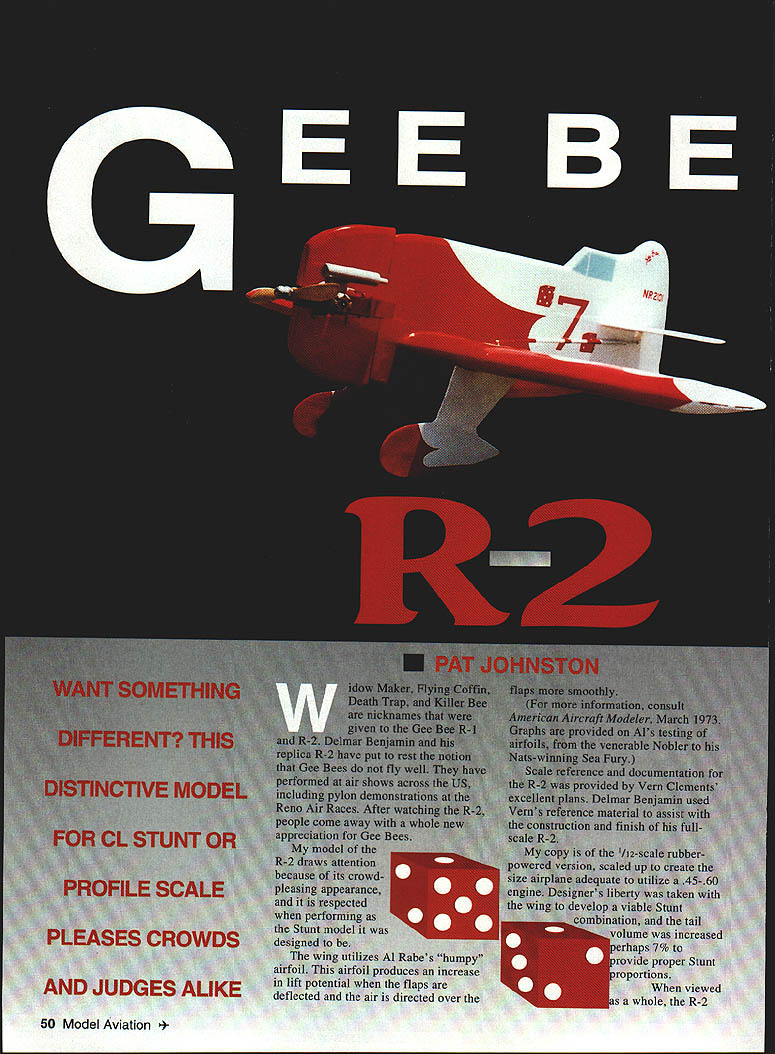
WIDOW MAKER, Flying Coffin, Death Trap, and Killer Bee were nicknames given to the Gee Bee R-1 and R-2. Delmar Benjamin and his replica R-2 have helped put to rest the notion that Gee Bees do not fly well. They have performed at air shows across the U.S., including pylon demonstrations at the Reno Air Races. After watching the R-2, people come away with a whole new appreciation for Gee Bees.
My model of the R-2 draws attention because of its crowd-pleasing appearance, and it is respected when performing as the stunt model it was designed to be.
The wing utilizes Al Rabe's "humpy" airfoil. This airfoil produces an increase in lift potential when the flaps are deflected and the air is directed over the flaps more smoothly. (For more information, consult American Aircraft Modeler, March 1973. Graphs are provided on Al's testing of airfoils, from the venerable Nobler to his Nats-winning Sea Fury.)
Scale reference and documentation for the R-2 was provided by Vern Clements' excellent plans. Delmar Benjamin used Vern's reference material to assist with the construction and finish of his full-scale R-2.
My copy is of the 1/2-scale rubber-powered version, scaled up to create a size airplane adequate to utilize a .45–.60 engine. Designer's liberty was taken with the wing to develop a viable stunt combination, and the tail volume was increased perhaps 7% to provide proper stunt proportions.
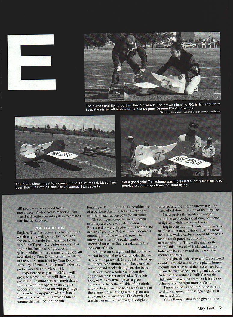
Want something different? This distinctive model for CL stunt or profile scale pleases crowds and judges alike. It still presents a very good scale appearance. Profile-scale modelers can install a throttle-control system to create a convincing airplane.
Construction
Engine
The first priority is to determine which engine will power the R-2. The choice was simple for me since I own two Super Tigre .46s. Unfortunately, this engine has been out of production for quite a while, so I recommend the Fox .40 modified by Tom Dixon or Lew Wollard, or the ST .51 modified by Tom Dixon or Tom Lay. If true "stunt grunt" is desired, go to Tom Dixon's Merco .61.
Experienced engine modifiers will provide a product that will do what is promised. I cannot stress enough that a few extra dollars spent on an engine properly set up for stunt will pay huge dividends in enjoyment with reduced frustrations. Nothing is worse than an engine that will not do the job.
Fuselage
This approach is a combination of a built-up stunt model and a stringer-and-bulkhead rubber-powered airplane. The stringers keep the weight down, and they are close to scale location. Because this weight reduction is behind the center of gravity (CG), stringers become a crucial part of the whole design. This allows the nose to be scale length; stretched noses on scale airplanes really look out of place.
A source for straight, light balsa is crucial in producing a stunt model that will fly up to its potential. Most of the sheeting should be no heavier than seven-pound stock; the lighter, the better.
Decide now whether to mount the engine on the right or left side. The left side, or "Texas style," gives a great appearance from the outside of the circle and the large fuselage helps blank some of the engine noise, giving a more pleasant showing to the audience. The drawbacks are that extra wingtip weight is required and the engine throws a gooey mess of oil down the side of the airplane.
I now prefer the right-side engine-mounting approach, sacrificing aesthetics to lighter weight and cleanliness.
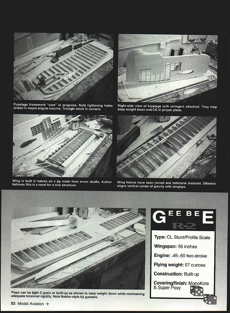
Begin construction by obtaining 3/4 x 3/8 maple engine-mount stock. I use a Dremel table saw with a carbide-tipped blade to rip maple stock purchased from our local hardwood store. This will establish the "core" thickness of 3/4 in. Lightening holes can be cut toward the rear of the mounts if desired.
The right-side sheeting and 3/32 plywood doubler are laid out over the plans. Engine mounts and the rest of the "core" are built up on the right-side sheeting and doublers. Note that the rudder is built flat on the right side and angled from the left side to achieve a bit of right-rudder offset.
Triangle stock is built into the corners to allow shaping the fuselage edges to a round section.
Some thought should be given to the landing-gear installation and mounting details.
Installation of the engine: I installed blind nuts into the maple motor mounts and cut the 4-40 cap screws so they would not penetrate through the backside.
The plywood doubler is open in the area of the fuel tank to allow the tank to be inset in the fuselage. This allows the centerline of the tank to be closely in line with the needle-valve assembly, producing more consistent engine runs. The left-side sheeting and doublers are then installed.
Now comes the fun part, especially for old-time free-flight builders: stringers! Before getting completely carried away, add 1/4 x 1/16 strip glue platforms where the stringers end. These are necessary to ensure a good glue joint.
Build up the vertical stabilizer and note that it is to have 1/8" left offset at its leading edge.
With the stringers installed, the fuselage is ready for final shaping and sanding. The fuselage will be noticeably stiff—especially for a profile airplane. This helps support flight-pressure loads on the flying surfaces during the intense parts of the pattern. Rigid fuselages fly better.
Wing
Standard D-tube construction is used, with some recent improvements.
Number-one priority: use a wing jig for framing each wing half. Commercial units are available; a homemade unit consisting of two stanchions made in a T section from 3/4" plywood supporting Easton X7 2014 arrow shafts will work—see your local archery pro shop. Rubber bands lash the shafts to the stanchions.
It's very important to keep the wing in the jig when the shear webs are installed. The webs bridge the 1/4" square spars and the front of the trailing-edge sheeting, and give the wing extreme rigidity. This helps maintain a very straight wing.
The leading-edge sheeting is installed to the second-to-last rib. A separate piece is used on the last bay. Before this is glued on, the 1/4" square leading edge is built up in the last bay with 1/8" scrap stock and shaped to a curved profile that tapers to nothing on both ends. This allows the sheeting to assume a gradual curve to the tip.
The spar is tapered to 1/8" at the tip in this last bay. The tip rib is undersized to allow complete tapering of the wing at the tip.
The wingtip gussets are Nobler-style. These take a little extra time to install, and they look great under the covering.
An adjustable leadout guide is necessary, along with an adjustable tip-weight box.
The wing halves are joined with one inch of dihedral. This aligns the vertical center of gravity with the wingtips. The R-2 flies with the tips level this way.
The flaps may be shaped from 1/4" lightweight C-grain stock, or can be built up as shown on the plans. Built-up flaps keep the weight reasonable while providing good torsional rigidity. Tail surfaces are constructed in the same manner.
Wing construction notes and tips:
- Keep the wing jig shear webs installed; they bridge and re-establish the spars and front and trailing-edge sheeting.
- Taper the spar in the last bay to 1/16" at the tip (plans show 1/16 tip taper).
- Use 1/16" grain vertical shear webs (main spar and trailing-edge shear webs).
- Use 1/16" trailing-edge sheeting (or 1/8" stock where called for).
- Install adjustable leadout guide and adjustable tip-weight box.
- Use Nobler-style tip gussets and a tapered leading edge built up in the last bay.
Landing Gear and Hardware
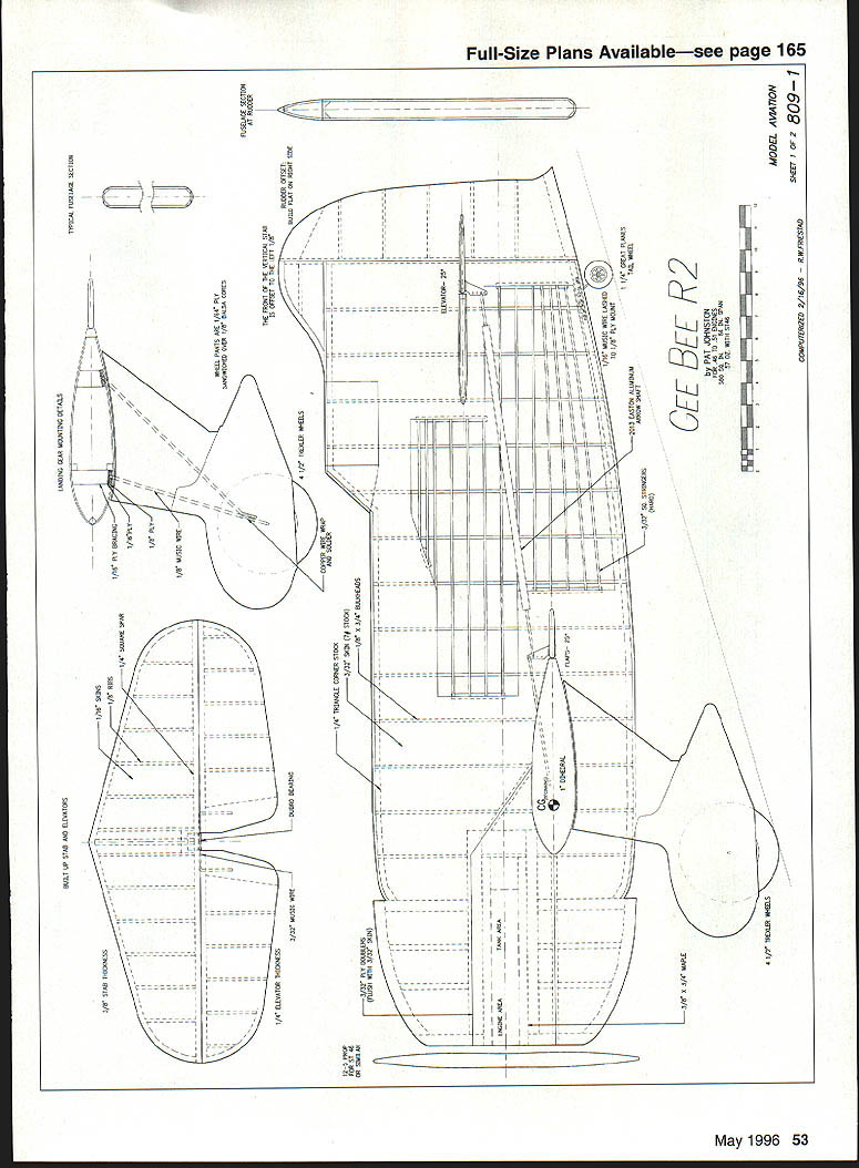
Landing-gear blocks are built up from 1/16" and 1/8" plywood to maintain the lightest possible weight. The 1/8" plywood reinforcing will support the ribs in the landing-gear bays. These gear mounts receive very little stress because of the 4-1/2" Trexler balloon wheels—next best thing to landing on a cloud!
Two pieces of 1/8" music wire are bound together with copper wire and soldered to form the landing-gear strut. A 1/8" balsa core is sandwiched with 1/64" plywood to complete the gear pants. Sandwiching the 1/8" ears inside the pants gives a nice, clean look to the landing-gear assembly. Flat gear straps secure the gear to the wing mounts.
The flap-to-elevator pushrod is made with 3/32" wire ends attached into an Easton XX75 2013 arrow shaft. This is an extremely lightweight shaft; most archery pro shops have sources for lots of damaged shafts. These damaged shafts are no good for archery but work perfectly well for pushrods and are a good alternative to more-expensive carbon-fiber shafts.
Cyanoacrylate (CyA) glue is used to glue the wing and tail assemblies into the fuselage. Sig's Epoxolite is used as a fillet material and as a strong joint reinforcer.
Specifications
- Type: CL Stunt / Profile Scale
- Wingspan: 56 inches
- Engine: .45–.60 two-stroke (.46–.51 recommended by plans)
- Flying weight: 57 ounces
- Construction: Built-up
- Covering/finish: MonoKote & K&B Super Poxy (author's choice)
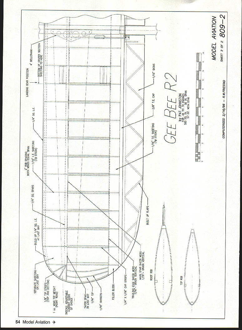
Plans and Drawing Notes
- For .46 to .51 engines.
- Sheet 1 of 2 — 809-1. Constructed 2/16/96 — R. W. Priestad.
- Sheet 2 of 2 — 809-2. Computerized 2/16/96 — R. W. Priestad.
Plan details and reminders:
- Landing-gear position: bottom of center-section sheeting to here.
- 1/4" square leading edge.
- Rib spacing: both wings equal span; separate sheeting build-up.
- Taper spar in last bay to 1/16" tip.
- 1/16" gussets.
- Filler block where shown.
- Install adjustable leadout guide of choice.
- 1/4" x 1/16" cap strips.
- Trailing-edge shear webs: 1/16" grain vertical.
- Main spar shear webs: 1/16" grain vertical.
- Built-up flaps; root rib and tip rib details per plans.
- 1/16" trailing-edge sheeting (1/8" stock where called).
- 3/8" T.E. cap and 1/16" skins as shown.
Finish
Options range from dope-and-silkspan to MonoKote, or whatever else can be thought up. Keep the finish as light as possible. The R-2 has a lot more fuselage area than almost any other subject—more fuselage area than any two Stunters. That is what makes it so much fun. So watch the finish weight.
I used MonoKote for minimal weight. The pushrod, tank, and inside of the engine area are painted with K&B Super Poxy (red and white). This provides a finished look to the whole package.
Trimming and Flying
- Engine mounts: be sure to mount the engine on aluminum pads. Windy Urtnowski sells a dandy set and also pads with 2° offset if desired.
- Trim: S-turns are normal for stunt. Start with the CG at 20% (about 2-1/4 inches from the leading edge). The final setting on my model is actually 24% (about 2-3/4 inches back).
- Handle-line spacing will be adjusted to establish a good groove coupled with a crisp corner. Wingtip weight should start with the right wing one ounce heavier at the tip. Play with the adjustable leadout guide until the tension is optimized.
- Position the takeoff roll slightly into the wind; the R-2 does not like any sort of tailwind.
- Landing: On asphalt, fly in with enough airspeed to touch down on the main gear and complete a prolonged rollout with the tail in the air, still flying. Gradually feed in down elevator until the tail quits flying and the tailwheel drops to the ground, completing the rollout. Bob Parker (many times Nats Stunt judge) says this pleases the judges and results in very high landing points.
I hope the R-2 provides you as much fun as it has for me. Putting the R-2 through the pattern is as much a thrill for the pilot as it is for the audience. Feel free to contact me if I can be of assistance.
Pat Johnston 7671 Iron Ct. Boise, ID 83704 (208) 322-6423
Product Sources
- Scale Gee Bee plans:
- Vern E. Clements
- 308 Palo Alto Dr.
- Caldwell, ID 83605
- Stunt Engines:
- Tom Dixon
- Box 671166
- Marietta, GA 30066
- Tom Lay
- T&L Specialties
- Box 6052
- Torrance, CA 90504
- Lew Wollard
- 3025 Locust
- Wichita, KS 67216
- Specialty parts:
- Windy Urtnowski
- PSP Products
- 93 Elliott Place
- Rutherford, NJ 07070
Transcribed from original scans by AI. Minor OCR errors may remain.

