
Gee Bee Senior: Sportster Model Y - Part 2
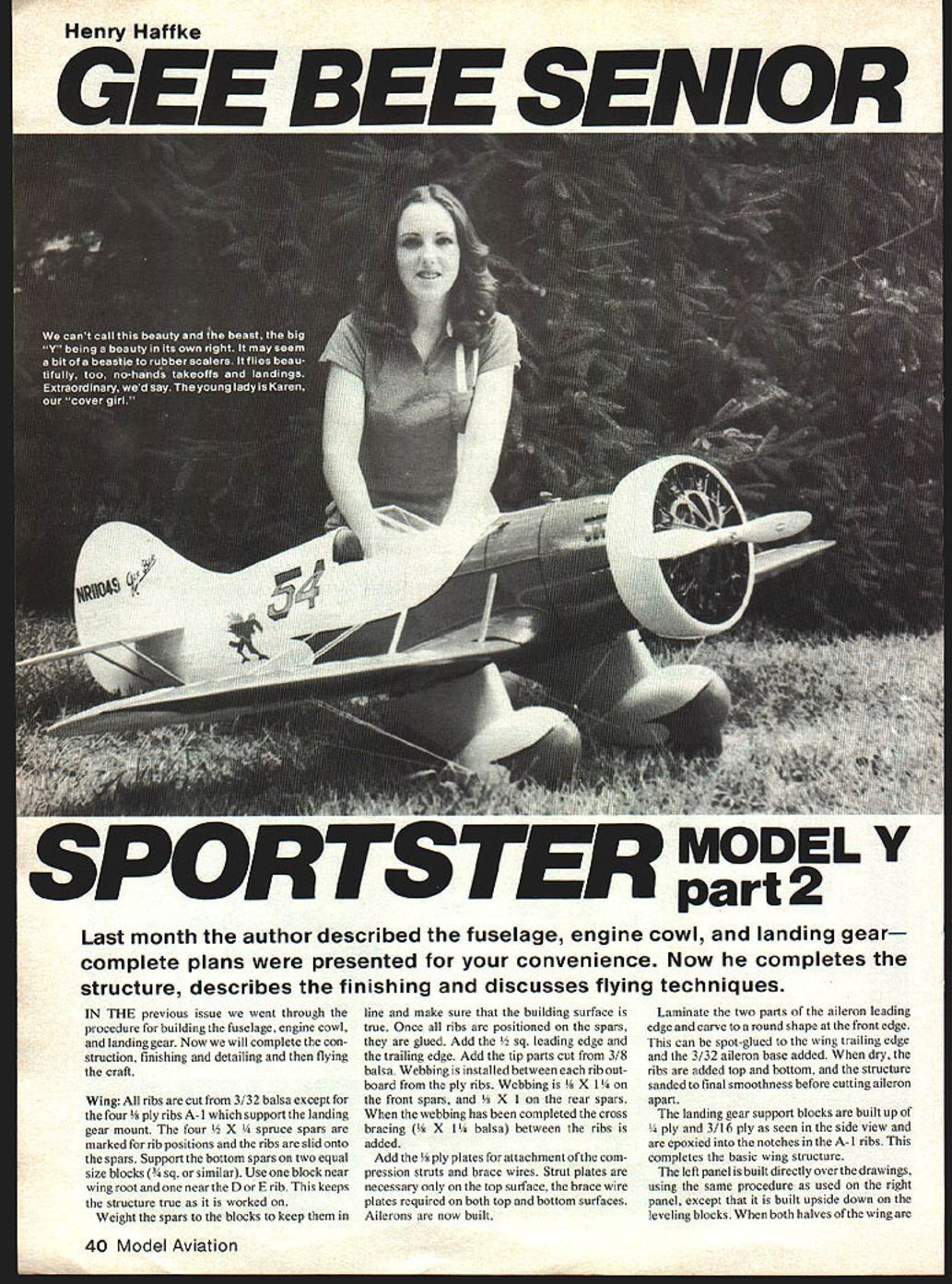
Last month the fuselage, engine cowl, and landing gear were described and complete plans were presented. This installment completes the structure, describes finishing and detailing, and discusses flying techniques.
Wing
- Rib stock: All ribs are cut from 3/32" balsa except for the four 1/4" plywood A-1 ribs that support the landing-gear mount.
- Spars: Four 1/4" x 1/4" spruce spars are marked for rib positions and the ribs are slid onto the spars.
- Building setup: Support the bottom spars on two equal-size leveling blocks (about 1/4" square or similar)—one near the wing root and one near the D/E rib—to keep the structure true while working. Weight the spars to the blocks and make sure the building surface is true.
- Assembly: Once all ribs are positioned, glue the spars. Add the 1/4" square leading edge and the trailing edge. Add the tip parts cut from 3/8" balsa.
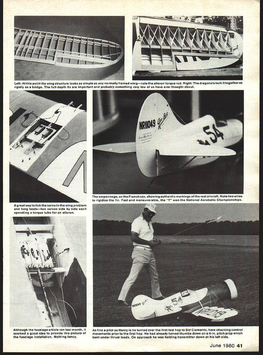
- Webbing and bracing: Install webbing between each rib outboard from the ply ribs: 1/2" x 1-1/4" on the front spars and 1/2" x 1" on the rear spars. When webbing is complete, add the cross bracing (1/8" x 1-1/4" balsa) between the ribs.
- Strut and brace plates: Add 1/4" plywood plates for attachment of the compression struts and brace wires. Strut plates are necessary on the top surface; brace-wire plates are required on both top and bottom surfaces.
Ailerons and Hinges
- Construction: Laminate the two parts of the aileron leading edge and carve the front edge to a round shape. Spot-glue this to the wing trailing edge and add the 3/32" aileron base. When dry, add the aileron ribs top and bottom and sand the structure to final smoothness before cutting the aileron apart.
- Hinge/torque tube: Use a short length of aluminum tube as a hinge pin. Install a pine block inboard at the front edge of the aileron to take the aluminum torque tube. Fit a 1" dowel on the end of the torque tube. Drill the pine block and tube so they are properly aligned. Install a screw from the bottom through the block and tube; use a long 4-40 bolt through the inner end of the torque tube.
- Linkage and servos: Use commercially available aileron connectors and 4-40 bolts and fit adjustable aileron cranks. A separate servo for each aileron is recommended. Flight loads will be reduced and redundancy increased by using two servos—ideally side-by-side each operating a torque tube. If that is not practical, two servos connected with a Y lead are preferable to a single servo.
Landing Gear and Wing Assembly
- Gear support blocks: Build landing-gear support blocks from 1/4" plywood and 3/16" plywood as shown on the side view and epoxy them into the notches in the A-1 ribs. This completes the basic wing structure.
- Left panel: Build the left panel directly over the drawings using the same procedure as for the right panel, but build it upside down on the leveling blocks.
- Dihedral braces: When both halves are joined, install dihedral braces. Two different braces (front and rear spars) are required to establish the correct dihedral. Support the wing on leveling blocks and block up the tip to hold everything square while drying.
- Center section: Finally, sheet the center section with 3/32" balsa.
Empennage (Stab, Elevator, Fin, Rudder)
- Construction: The stabilizer and elevator are built similarly to the fin and rudder described previously. They can be built-up from parts shown on the drawings or made solid from sheet stock.
- Hinges: Scale hinges or wire hinge pins are shown on the rudder drawings; commercial hinges may be used if preferred.
- Horns: Elevators are connected to a Sig elevator horn. Use an offset horn if you want a completely internal installation.
- Final fit: With tail surfaces installed, fit the wing, add stringers to the fuselage, and sand everything to final smoothness.
Radio Installation
- Placement: Install equipment to achieve the center-of-gravity shown on the plans. Typically the servos and receiver go between F-4 and F-5; the battery can be located wherever necessary to help balance.
- Mounting: Mount everything per the manufacturers' recommendations. Ensure pushrods connect to give correct movement relative to the control sticks.
- Pushrods: Use stiff pushrods—at least 1/8" dowel.
Finishing
- Covering: In the author's model the entire airframe was covered with white Permagloss by Coverite and trimmed with red Super MonoKote. Patterns were cut from paper for the wing panels so all four would be identical. A paper pattern was also made for the two fuselage sides. Markings were cut from red MonoKote; the Gee Bee logo on the fin is black MonoKote. Automotive striping tape was used for pin striping.
- Paint/doped parts: Permagloss gives a realistic appearance and MonoKote trim yields a light finish. Only the wing fillet, landing-gear fairings, and engine cowl were doped. This finish kept the model under the 15 lb. target weight; a full doped finish would have put it over.
- Tips: Masking and paper patterns help make identical panels and fuselage sides.
Detailing
- Compression and stab struts: Compression struts are made from streamlined aluminum tubing and held with short sheet-metal screws. Stab struts are shaped from spruce—do not omit them if you build up the stabilizer; they add considerable strength.
- Brace wires: Brace wires add a distinctive appearance. Make them from elastic cord found in fabric shops. Make an aluminum bracket of thin stock that extends through the fuselage about 1/8" to accept the brace-wire ends. Drill three holes in each end of the bracket for wire attachment and use quick-links for realistic connectors. Thread brace wires through the wing and landing-gear fairing and attach them to the base of the opposite landing-gear mount block with an aluminum bracket screwed to the block.
- Cockpit and louvers: If racing with the front cockpit covered, make the cover from 1/32" plywood and attach with small sheet-metal screws. Louvers behind the cowl are formed from thin aluminum with tabs on each end; cut slits in the covering and balsa for each louver and secure them (the author used a product called Hot Stuff). Long piano-type hinges on the fuselage sides can be made by slicing plastic tubing and threading it on music wire.
- Dummy radial engine: A dummy radial is essential for realism. Use the drawings for the engine shroud and Wasp cylinders. Make a plug and vacuum-form the cylinders, back them with 1/8" balsa, and glue to the rear of the shroud. The shroud is two layers of 1/8" balsa with a 1/16" plywood backing ring; use 1/8" dowel for pushrods. Paint the shroud flat black and the cylinders gloss black.
Flying
- Handling: A 1/4-scale low-wing model has very realistic handling. Wing loading is low so little speed is needed to take off.
- Test pilot: The author's first flights were at the Clayton R/C Club field with test pilot Syd Clements flying initial hops and trimming. Syd's experience allowed rapid evaluation and setup tweaks such as engine offset.
- Propellers and engine: Initial attempts with a thin-bladed 16x4 prop showed tip flexing; a 14x6 produced adequate performance. Later a heavier 16x4 was found to be well suited.
- First flights: Taxi and takeoff were easy into wind; the model climbed out majestically and flew hands-off straight ahead once trimmed. Aileron response was reported as slightly sluggish until linkages and servo tray were secured.
- Tank and range: The first dead-stick landing revealed an empty tank. A subsequent full-scale pattern flight left about 6 oz. in the tank—an acceptable reserve for the Webra .91 used.
- Pilot notes: The author experienced a rough first takeoff due to over-rotation but recovered by lowering the nose to gain speed. After tightening the aileron servo tray and locknuts on the 4-40 bolts through the torque rods, aileron response improved noticeably.
Contest experience and radio issues
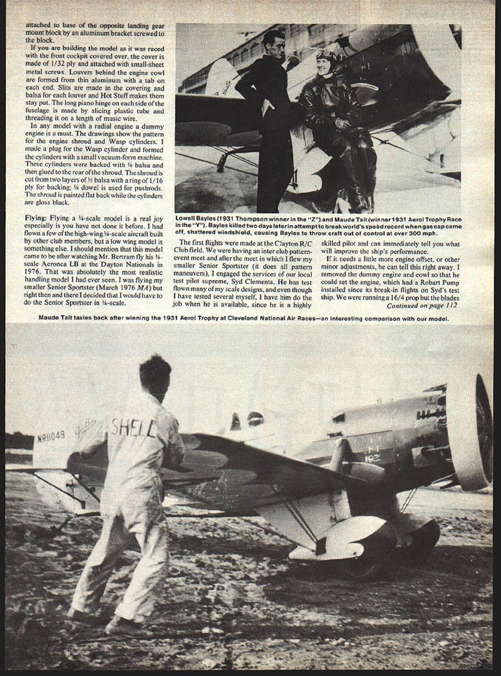
- Rhinebeck Classic: At Rhinebeck the Senior Sportster earned a static score of 90 and received the highest flight score on the first flight. On a later flight aileron control was lost due to a faulty radio; the model was damaged but repairable in four evenings.
- Repeat intermittent failures: Similar loss-of-aileron-control incidents occurred on subsequent flights. Testing the radio in another ship showed no faults, but substituting a different, reliable radio solved the problem in the long term.
- Bealeton contest: After further testing (including flights in gusty, drizzly conditions with a 16x4 prop), the model scored 94 static at Bealeton and won the Quarter Scale event, taking the contest's grand prize—a 5-channel system.
Closing / Documentation
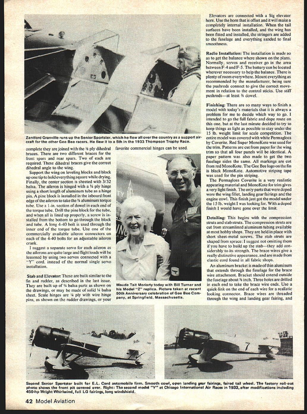
- The Senior Sportster performs beautifully and recalls 1930s lines. The author offers to share his extensive collection of photographs for those who need scale documentation for contests; contact details are available on the plans/club listing.
- The author hopes builders enjoy the model as much as he has.
This completes the construction, finishing, detailing, and flying notes for the Gee Bee Senior: Sportster Model Y.
Transcribed from original scans by AI. Minor OCR errors may remain.

