
GEE BEE Z
Henry A. Haffke
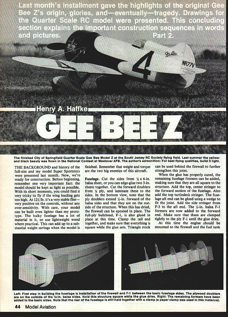
THE BACKGROUND
The background and history of the full-size Super Sportsters were presented last month. Now we're ready for construction. Before beginning, remember one very important fact: the model should be kept as light as possible. With its short moment arms it can be very tricky to fly if the wing loading gets too high. At about 12½ lb it is a very stable flier — very positive on the controls; with higher weight it can become overly sensitive. With care, your model can be built even lighter than my prototype. The bulky fuselage contains a lot of material, so use lightweight wood where practical — this can add up to substantial weight savings. Remember that weight and torque are the two big enemies of this aircraft.
Fuselage
Cut the sides from 1/4 x 6-in. balsa sheet, or edge-glue two 3-in. sheets together. Cut the forward doublers from 1/8-in. ply and laminate these to the sides. In the bottom view note that the ply doublers extend 1/4-in. forward of the balsa sides and that they are on the outside of the structure. When this has dried, epoxy the firewall in place. Glue the full-ply bulkhead F-1 in place at this time. Clamp the tail end together and make sure everything is square while the glue sets. Triangle stock can be used behind the firewall to further strengthen this joint.
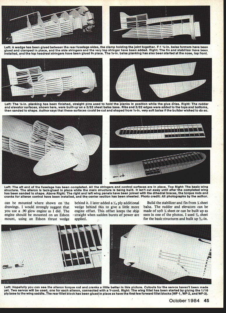
When the glue has properly cured, add the remaining fuselage formers, making sure they are all square to the structure. Add the top center stringer to the forward section of the fuselage and the top turtledeck stringer. The fuselage aft end can be glued using a wedge to fit the joint. Add the side stringer from F-3 to the aft end. The 1/2-in. balsa F-1 formers are now added to the forward end — clamp them tightly to the ply F-1 until the glue dries.
Mount the engine to the firewall and locate the fuel tank where shown on the drawings behind it. I later added a 1/16-in. ply wedge behind the engine to give a little more offset; this helps keep the ship straight when sudden bursts of power are applied. I strongly suggest using a .90 glow engine, mounted on an Edson mount with an Edson thrust wedge.
Build the stabilizer and fin from 1/4-in. sheet balsa. The rudder and elevators can be cut from very soft 1/8-in. sheet or built up. I used 3/32-in. sheet for the basic structures and built up 1/8-in. ribs and outer edges on both top and bottom for better scale accuracy and less weight. When finished, sand to final shape and glue the fin and stabilizer in position. The turtledeck stringers can be added at this time.
Sheet or plank the forward end of the fuselage with 1/8-in. balsa. The top front is planked back to F-5 and the sides are planked back to F-3. When the glue has dried, sand the structure to final shape.
Engine mount and controls
The plans and photographs suggest the use of a .90 glow engine installed on an Edson mount with an Edson thrust wedge. For additional offset, add a thin ply wedge behind the mount. Radio components should be installed as far forward as practical: servos on a ply tray, battery ahead of the elevator servo alongside the fuel tank, and the receiver tucked between the main fuselage side and the outer sheeting under the servo tray. I used a cedar arrow shaft for the elevator pushrod; the rudder is actuated by steel cables and the throttle by a Ny-Rod.
WING
Select a piece of hard balsa for the spars and the leading edge. Cut all ribs from the appropriate materials and test-fit the spar cutouts. A useful trick is to slip each rib onto a short piece of spar material as it is cut; stacking the ribs on the short spar pieces allows very accurate spar cutouts and easy sanding of matching cutouts. Tip ribs, which have smaller cutouts, cannot be stacked with the others.
Trim the spar tips as shown on the plans and mark each spar for all rib locations. Slide the ribs on the spars and locate each rib in its proper position on the markings. Make sure you are working on the correct panel.
Cutouts for servos should be made as required. Two servos will be used; the ailerons are connected with a Y-cord.
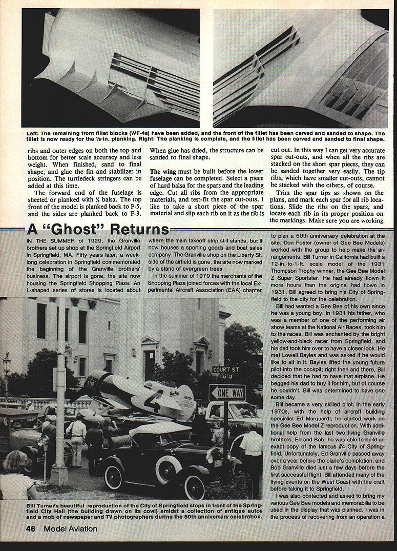
The wing fillet: glue a 1/16-in. ply base at the wing saddle. Glue the rear fillet block in place and install the forward fillet blocks (WF-1 through WF-4). Carve and sand the fillet to shape and plank it with 1/8-in. balsa strips. Final carving and sanding will produce the finished fillet.
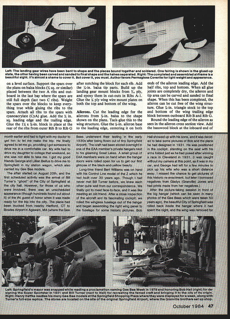
On a level surface, support the spars over the plans on balsa blocks (3/4-in. sq. or similar) placed between the two A ribs and outboard in the last bay where the spars are still full depth (last two C ribs). Weight the spars over the blocks to keep everything true while gluing the ribs to the spars. Attach all ribs to the spars with cyanoacrylate (CyA) glue. Add the 1/2-in. sq. leading edge and the trailing edge. Glue a 1/8 x 1/2-in. block in place at the rear of the ribs from outer Rib B to Rib G after notching the block for each rib. Add the 1/4-in. balsa tip parts. Build landing gear mount blocks from 3/4-in. ply and epoxy them into cut-outs in Ribs A-1. Glue 1/16-in. ply wing wire mount plates on both the top and bottom of the wing.
Ailerons
Cut the leading edge for the ailerons from 3/8-in. balsa to the shape shown on the plans and tack-glue it to the wing structure. Glue the 1/8-in. aileron base to the leading edge, centering it on both ends. Add the half ribs top and bottom. When all glue joints are completely dry, carve and sand the aileron and tip area to final shape. Cut the aileron free of the wing structure. Glue 1/4-in. triangle stock to the top and bottom of the wing trailing edge block between outboard Rib B and Rib G. Round the leading edge of the aileron per the aileron cross-section view and add the basswood block at the inboard end of the aileron.
WING FILLET — DETAILED CONSTRUCTION
Start with a section of 1/16-in. ply for the fillet base and glue it to the wing saddle from the rear of the saddle, extending forward as required by the plans. When gluing, attach the wing to ensure the exact dihedral angle and keep it attached until the joint has completely dried.
Fill in between the stringers behind F-3 with 1/8-in. balsa where the aft end of the fillet meets the fuselage. Glue fillet parts WF-5, WF-6 and WF-7 in place as shown on the plans. Glue WF-1 in place against the fuselage, tapering its upper edge to fit the fuselage curve; trim and fit pieces of 1/8-in. balsa to fill the triangular opening created inside and below WF-1. Glue WF-2, WF-3 and several WF-4s to WF-1; WF-4s extend to the outer edge of the ply fillet base. Install the rear fillet block (WF-8) behind WF-7. When dry, plank the fillet with 1/8 x 3/8-in. balsa strips and finish-shape and sand to a beautiful fillet.
LANDING GEAR
Bend the 3/16-in. wire landing gear and wire parts. Bind and solder the front and rear wires together only after installing them in the wings to ensure proper alignment. Landing gear fairings are built up from ply and balsa parts cut from the plans. Laminate the parts for each fairing half together and weight or clamp until the glue has dried. Use short sections of 1/8-in. dowel to peg the parts together — one dowel in the front and another in the rear section of the wheel fairing — to keep the halves aligned. Tack-glue the two halves of each fairing together; carve and sand to final shape. Form and add the fairing caps after installing them on the landing gear wires.
Install the wheels with a wheel collar on each side to keep them centered in the fairings. When finished, sandwich the fairing halves around the landing gear wires and spot-glue in place so they can pop apart in the event of a rough landing. The cuff is added after final assembly.
ENGINE COWL
Cut the cowl rings from the materials shown on the plans and patterns. Laminate the front and rear rings together and join them with lengths of 1/4-in. sq. balsa; make sure everything is square while drying. When dry, sheet or plank the cowl with 1/16-in. balsa and carve and sand to final shape. If you prefer not to build wood wheel fairings and cowl, fiberglass parts are available from T&D Fiberglass Specialties, 30925 Block, Garden City, MI 48135.
Finish the tail surfaces and add elevators and rudder to the stab and fin. The plans show parts for a ply rudder horn for correct scale; it works well with steel cables for rudder actuation. A commercial elevator horn may be installed between the two elevator halves.
RADIO INSTALLATION
Refer to the drawings and photos. Install radio components as far forward as possible. Mount servos on a ply tray as shown on the bottom-view drawings. I used larger servos on the elevators and regular-size servos for rudder and throttle. Place the battery ahead of the elevator servo alongside the fuel tank and tuck the receiver between the fuselage side and the outer sheeting under the servo tray. Use a cedar arrow shaft for the elevator pushrod; the rudder is best actuated by steel cables. Use a Ny-Rod for throttle actuation.
FINISHING AND COVERING
A lightweight finish is important. For a scalelike fabric finish I used Coverite's pre-painted Permagloss fabric (Cub Yellow matched well to the full-scale Model Z). I sealed the structure with a coat of Balsarite and covered the model with the Permagloss material.
When covering sheeted areas, take care to avoid trapping air. Cut a piece slightly larger than the area, tack it down through the middle, then work out in both directions pulling the material tight and ironing it down. Do not rush; avoid ironing too large a section at once. Keep the iron temperature around 225°–250° F when ironing over sheeted areas to activate the adhesive without trouble.
Trim excess covering by slipping a thin piece of cardboard or plywood under the material, use a straightedge and sharp knife to cut away excess, and iron down the remaining edge for a neat finish. Always start covering on the underside, work up the sides, and finish with the top. With planning, final seams can match panel seams on the full-size aircraft for realistic appearance.
Mask patterns were made from paper for the black trim on the wings and fuselage to ensure identical trim on all panels. Mask the areas, brush on Primex as a base, then spray two light coats of Black Baron Black and top with Black Baron Clear when dry. Large registration and racing numbers were cut from pressure-sensitive Mylar and pin-striped with red striping tape. Small lettering was done by hand. The trim on the black painted areas was done with thinned K&B epoxy; the yellow fuselage and landing gear markings were done with Randolph butyrate dope, except the rudder markings which used drawing ink. Clear Randolph dope was applied over lettering to seal edges.
DETAILING
Detailing can be as extensive as desired. I installed flying and landing wires made of elastic cord with silver sleeves fitted for attachment to an aluminum plate that extends about 1/2 in. through the fuselage skin. A basswood fairing was carved to cover the wire attachment plate; the cowl rod fits through this fairing and holds it in place. Thin strips of Permagloss were cut and applied over every rib in the wing and tail surfaces to simulate rib tape. Streamline aluminum tubing was used for stabilizer struts and a ply fairing epoxied to the tail skid with aluminum bands for a realistic appearance.
The buckles holding the metal panels behind the cowl were reproduced from a real buckle by making a 1/4-scale sketch and cutting parts from hard 1/32-in. balsa and 1/16-in. basswood. A section of paper clip formed the clamping wire and small dots of glue simulated screws. These were painted aluminum and epoxied to the model.
The oil cooler was built from the plans and made removable. A 1/8-in. ply plate in the cooler bottom takes a long sheet-metal screw fastening it to a ply plate in the structure; a 1/8-in. dowel near the aft end keeps it aligned. A dummy engine was built up of ply and balsa for the crankcase with Williams Bros. Wasp cylinders around it (two cylinders left off for cooling). The dummy engine fits on three dowels extending from the firewall; the cowling holds it in place. A dummy Curtiss prop was carved from basswood.
The cockpit cover was formed from three pieces as on the full-size Model Z: back section formed around the headrest bulkhead, a bottom section curving around the cockpit opening back to the rear piece, and a top curved piece cut from a molded canopy. Glue the pieces with R/C 56 glue. Drill tiny holes around the overlap areas and install short pieces of straight pin heads to simulate screws. Install a Lowell Bayles figure in the cockpit before closing the enclosure — don't forget his goggles.
FLYING
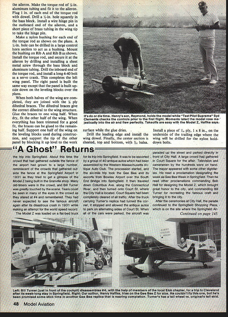
If you have built the model straight and kept the weight to 12 lb or under, you should not have too much trouble flying it if you are a competent pilot. Be sure the model balances where shown on the plans; do not attempt to fly it if the balance point is behind the specified location. If unsure, have a good pilot test-fly it.
On takeoff, apply power with a touch of up-elevator to keep the tail down as it starts to roll. As it gains speed, let up on the elevator and the tail will come up; when straight, it will lift off with a touch of up-elevator. Do not try to force it off before flying speed is attained.
Once airborne, the model is very fast and responsive but stable — not touchy on the controls. For landings, bring it in a little fast until you become familiar with its characteristics and hold it off until it slows and settles. Every grass landing on my model has been perfect; it has flipped only once after touchdown in a crosswind, causing minor paint damage. I have really enjoyed flying the Model Z and expect anyone who builds one to enjoy it as much. If you wish to compete, I can help with documentation and photos. Contact: Henry A. Haffke, 1038 West Elmer Rd., Vineland, NJ 08360.
"A GHOST" RETURNS
About a month earlier I had to fight with my doctor to let me make the trip to Springfield. My wife had to drive my daughter to college that weekend, so she could not take me. I got my good friends George and Julian Beituss to drive me in my station wagon, which also carried my Gee Bee models.
The affair started on August 20th. The first scheduled activity was the arrival of Bill Turner's "ghost" of the City of Springfield at City Hall. The plane had been trucked from nearby Hartford, CT to Bowles Airport in Agawam, MA (where the Gee Bees underwent testing in the early 1930s). The craft had been stored overnight in an EAA member's private hangar. A small group of EAA members were on hand when the hangar doors were rolled open and we first glimpsed the black-and-yellow beauty.
Long-time friend Bert Williams was on hand with his control-line model of the Z, which he had built over 30 years before. Though I had never met Bill Turner in person, we had corresponded and it was like meeting an old friend. After close inspection of the aircraft and its fascinating cockpit, we rolled the wingless fuselage out of the hangar and began assembling the right wing panel to the fuselage for historic pictures. Bob Hall arrived with his sons and posed in the cockpit as he had after winning a Cleveland race in 1931. I missed getting pictures of that reenactment but later borrowed negatives from Gladys (Granville) Jones and had prints made.
After picture-taking in front of the hangar, the City of Springfield rolled back inside the hangar where it had spent the night; the wing was then removed for the trip into Springfield. By that time a large crowd had gathered outside the airport fence, reminiscent of the Springfield Airport crowds in 1931. Many old-timers were in attendance and Bill Turner was visibly moved. Tears were seen in many eyes as people remembered #4 and its 1931 crash during a world speed-record attempt.
The Model Z was loaded on a flat-bed truck for its trip into Springfield and escorted by about 40 antique autos assembled by the Western Massachusetts Antique Auto Club. The six-mile procession went from Bowles Airport, over the South End Bridge into Springfield, down Columbus Ave. along the Connecticut River, and onto Court St. Court Square was cleared of traffic; after the truck stopped, the antique autos parked on alternating sides of Court St. The aircraft was paraded up the street and parked directly in front of City Hall. A large crowd, television crews and many cameramen were on hand. The mayor and other dignitaries read proclamations designating the week as Gee Bee Week in Springfield and commending Bob Hall and Bill Turner for their contributions.
After the ceremonies at City Hall, the parade continued to the Springfield Shopping Plaza, which sits on the site where the Springfield Airport once was located.
Transcribed from original scans by AI. Minor OCR errors may remain.

