
Genie Redux
An award-winning design several years in the making
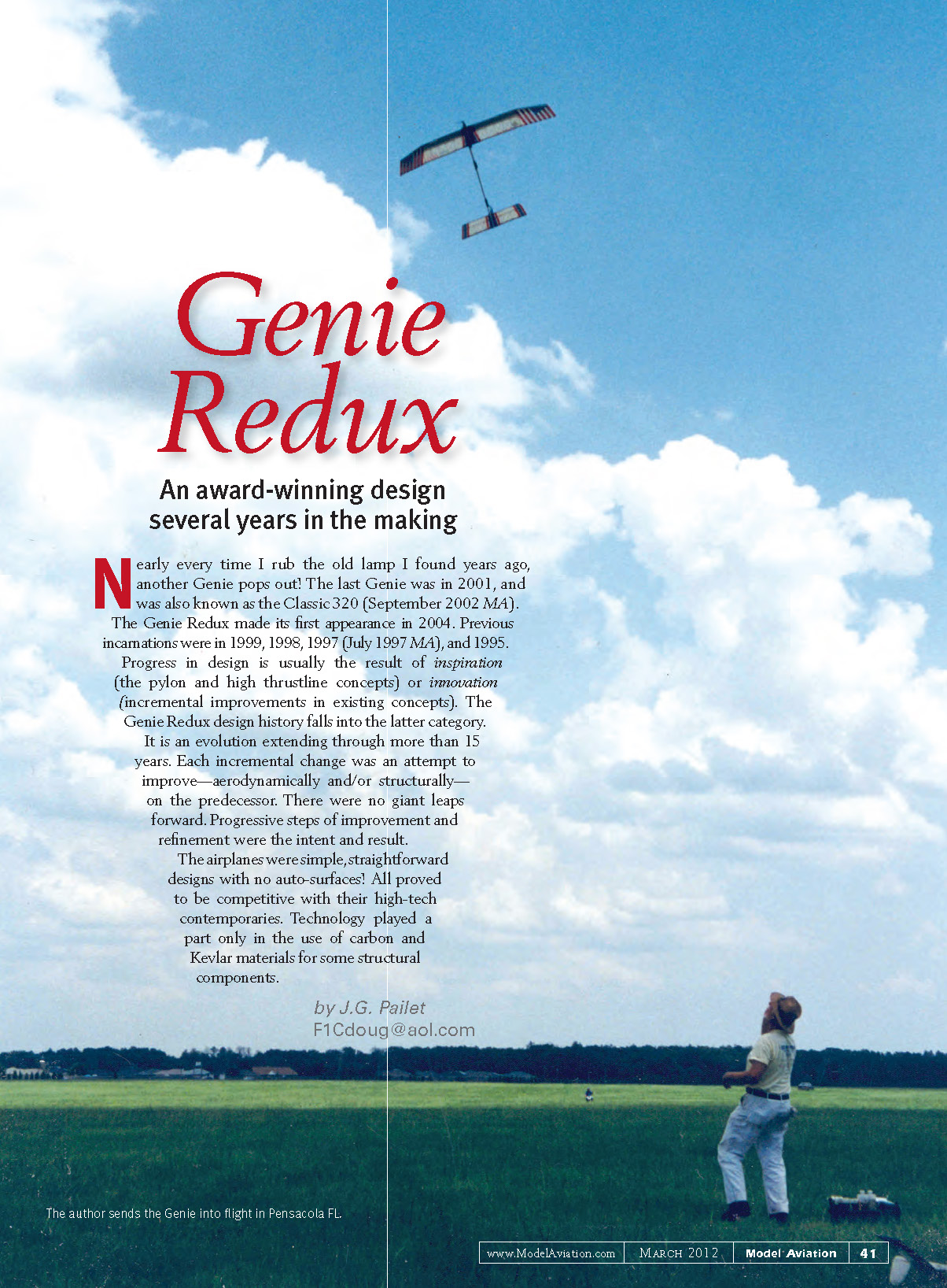
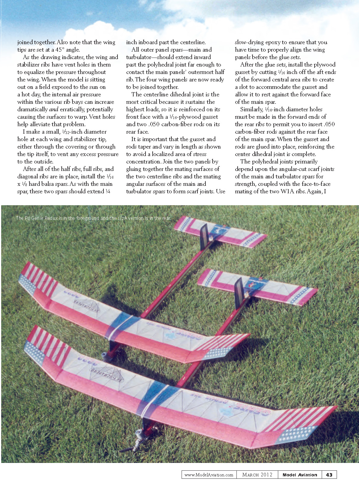
Nearly every time I rub the old lamp I found years ago, another Genie pops out! The last Genie was in 2001 and was also known as the Classic 320 (September 2002 MA). The Genie Redux made its first appearance in 2004. Previous incarnations were in 1999, 1998, 1997 (July 1997 MA), and 1995.
Progress in design is usually the result of inspiration (the pylon and high thrustline concepts) or innovation (incremental improvements in existing concepts). The Genie Redux design history falls into the latter category.
It is an evolution extending through more than 15 years. Each incremental change was an attempt to improve—aerodynamically and/or structurally—on the predecessor. There were no giant leaps forward. Progressive steps of improvement and refinement were the intent and result.
The airplanes were simple, straightforward designs with no auto-surfaces. All proved to be competitive with their high-tech contemporaries. Technology played a part only in the use of carbon and Kevlar materials for some structural components.
by J. G. Pailet F1Cdoug@aol.com
I must share credit for the success of these models with my regular design and engineering consultants: Don Broggini, John Carbone, Bob Hatscheck, and Joe Mollendorf. Thanks, guys! Another thank-you goes to Jim O’Reilly for the excellent computer-generated plans. The Genie Redux was one of the National Free Flight Society’s 2010 Models of the Year.
The Wing
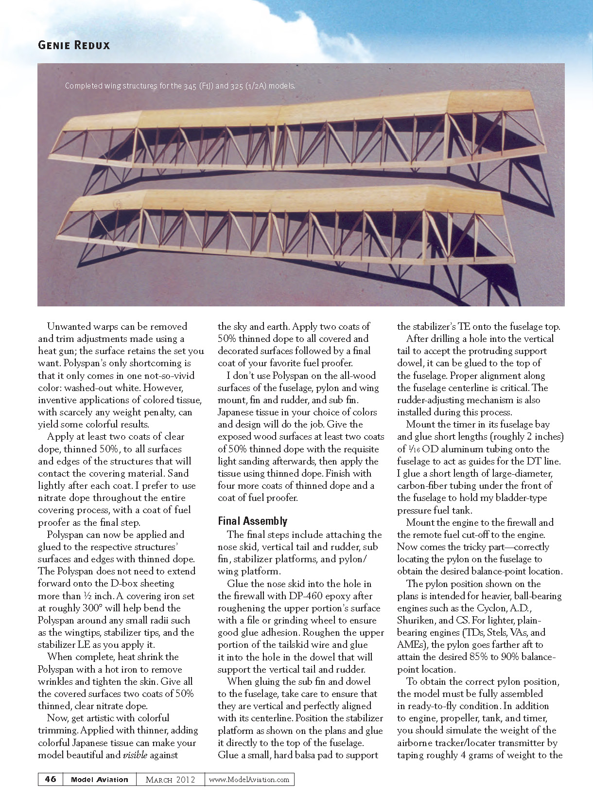
As depicted on the plans, the wing features a sheet-balsa-covered forward portion to form a standard D-box structure. However, the underlying turbulator-spar structure has demonstrated its strength adequacy in earlier designs.
I prefer the sheeted version for its cleaner aerodynamic characteristics. You will save some weight by eliminating the sheeting, but be sure to alter the forward rib profile to compensate for the lack of sheeting and to relocate the turbulator spars accordingly. The following text assumes you choose the D-box structure.
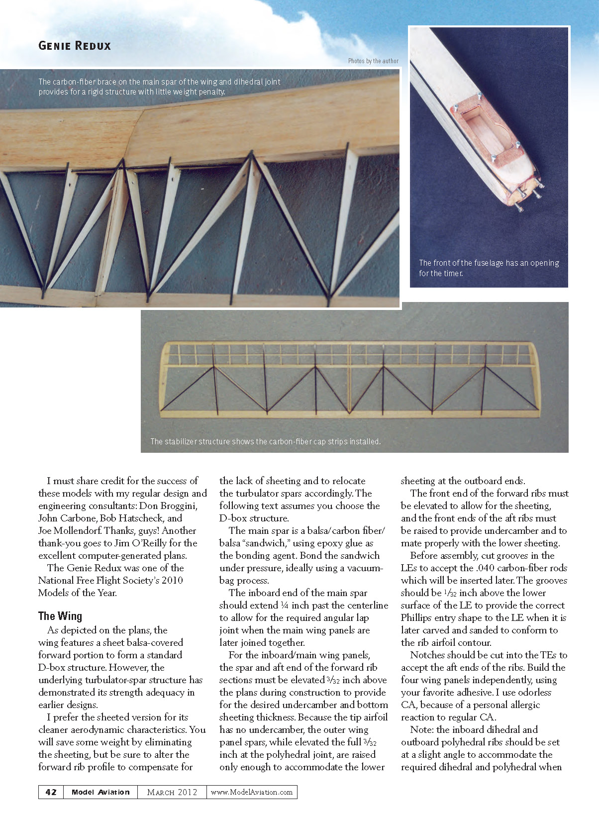
The main spar is a balsa/carbon-fiber/balsa sandwich, using epoxy as the bonding agent. Bond the sandwich under pressure, ideally using a vacuum-bag process.
The inboard end of the main spar should extend 1/4 inch past the centerline to allow for the required angular lap joint when the main wing panels are later joined together.
For the inboard/main wing panels, the spar and aft end of the forward rib sections must be elevated 3/32 inch above the plans during construction to provide for the desired undercamber and bottom sheeting thickness. Because the tip airfoil has no undercamber, the outer wing panel spars, while elevated the full 3/32 inch at the polyhedral joint, are raised only enough to accommodate the lower sheeting at the outboard ends.
The front end of the forward ribs must be elevated to allow for the sheeting, and the front ends of the aft ribs must be raised to provide undercamber and to mate properly with the lower sheeting.
Before assembly, cut grooves in the LEs to accept the .040 carbon-fiber rods which will be inserted later. The grooves should be 1/32 inch above the lower surface of the LE to provide the correct Phillips entry shape to the LE when it is later carved and sanded to conform to the rib airfoil contour.
Notches should be cut into the TEs to accept the aft ends of the ribs. Build the four wing panels independently, using your favorite adhesive. I use odorless CA because of a personal allergic reaction to regular CA.
Note: the inboard dihedral and outboard polyhedral ribs should be set at a slight angle to accommodate the required dihedral and polyhedral when joined together. Also note that the wing tips are set at a 45° angle.
As the drawing indicates, the wing and stabilizer ribs have vent holes in them to equalize the pressure throughout the wing. When the model is sitting out on a field exposed to the sun on a hot day, the internal air pressure within the various rib bays can increase dramatically and erratically, potentially causing the surfaces to warp. Vent holes help alleviate that problem.
I make a small, 1/32-inch diameter hole at each wing and stabilizer tip, either through the covering or through the tip itself, to vent any excess pressure to the outside.
After all of the half ribs, full ribs, and diagonal ribs are in place, install the 1/16 x 1/8 hard balsa spars. As with the main spar, these two spars should extend 1/4 inch inboard past the centerline.
All outer panel spars—main and turbulator—should extend inward past the polyhedral joint far enough to contact the main panels' outermost half rib. The four wing panels are now ready to be joined together.
The centerline dihedral joint is the most critical because it sustains the highest loads, so it is reinforced on its front face with a 1/16-inch plywood gusset and two .050 carbon-fiber rods on its rear face.
It is important that the gusset and rods taper and vary in length as shown on the plans to avoid a localized area of stress concentration. Join the two panels by gluing together the mating surfaces of the two centerline ribs and the mating angular surfaces of the main and turbulator spars to form scarf joints. Use slow-drying epoxy to ensure that you have time to properly align the wing panels before the glue sets.
After the glue sets, install the plywood gusset by cutting 1/16 inch off the aft ends of the forward central-area ribs to create a slot to accommodate the gusset and allow it to rest against the forward face of the main spar.
Similarly, 1/16-inch diameter holes must be made in the forward ends of the rear ribs to permit you to insert .050 carbon-fiber rods against the rear face of the main spar. When the gusset and rods are glued into place, reinforcing the center dihedral joint is complete.
The polyhedral joints primarily depend upon the angular-cut scarf joints of the main and turbulator spars for strength, coupled with the face-to-face mating of the two W1A ribs. Again, I recommend using slow-drying epoxy to allow time to align the respective inboard and outboard wing panels.
Additional strengthening is achieved by gluing the inward-extended ends of the spars to the most-outboard half ribs of the main wing panels. You should now have a one-piece, assembled wing, ready for the LE .040 carbon-fiber rod and the D-box sheeting.
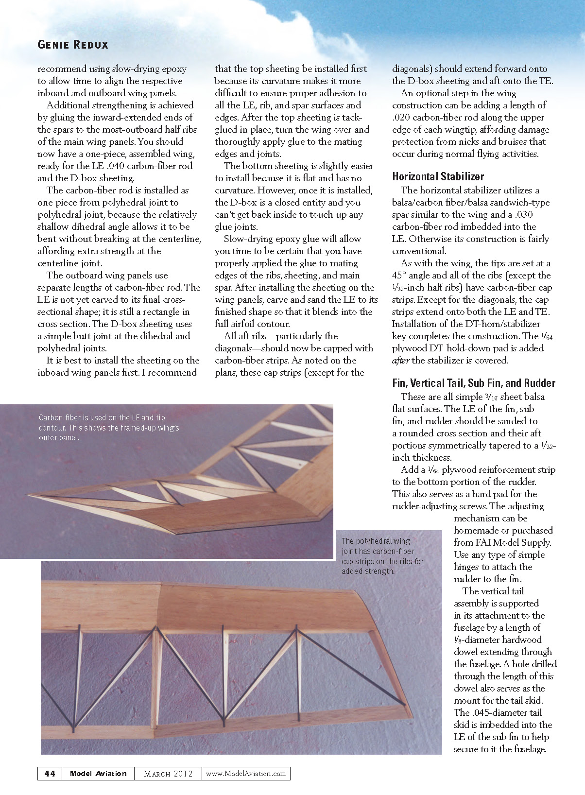
The carbon-fiber rod is installed as one piece from polyhedral joint to polyhedral joint because the relatively shallow dihedral angle allows it to be bent without breaking at the centerline, affording extra strength at the centerline joint.
The outboard wing panels use separate lengths of carbon-fiber rod. The LE is not yet carved to its final cross-sectional shape; it is still a rectangle in cross section. The D-box sheeting uses a simple butt joint at the dihedral and polyhedral joints.
It is best to install the sheeting on the inboard wing panels first. I recommend that the top sheeting be installed first because its curvature makes it more difficult to ensure proper adhesion to all the LE, rib, and spar surfaces and edges. After the top sheeting is tack-glued in place, turn the wing over and thoroughly apply glue to the mating edges and joints.
The bottom sheeting is slightly easier to install because it is flat and has no curvature. However, once it is installed, the D-box is a closed entity and you cannot get back inside to touch up any glue joints.
Slow-drying epoxy will allow you time to be certain that you have properly applied the glue to mating edges of the ribs, sheeting, and main spar. After installing the sheeting on the wing panels, carve and sand the LE to its finished shape so that it blends into the full airfoil contour.
All aft ribs—particularly the diagonals—should now be capped with carbon-fiber strips. As noted on the plans, these cap strips (except for the diagonals) should extend forward onto the D-box sheeting and aft onto the TE.
An optional step in the wing construction is adding a length of .020 carbon-fiber rod along the upper edge of each wingtip, affording damage protection from nicks and bruises that occur during normal flying activities.
Horizontal Stabilizer
The horizontal stabilizer utilizes a balsa/carbon-fiber/balsa sandwich-type spar similar to the wing and a .030 carbon-fiber rod imbedded into the LE. Otherwise its construction is fairly conventional.
As with the wing, the tips are set at a 45° angle and all of the ribs (except the 1/32-inch half ribs) have carbon-fiber cap strips. Except for the diagonals, the cap strips extend onto both the LE and TE. Installation of the DT-horn/stabilizer key completes the construction. The 1/64-inch plywood DT hold-down pad is added after the stabilizer is covered.
Fin, Vertical Tail, Sub Fin, and Rudder
These are all simple 3/16-inch sheet balsa flat surfaces. The LE of the fin, sub fin, and rudder should be sanded to a rounded cross section and their aft portions symmetrically tapered to a 1/32-inch thickness.
Add a 1/64-inch plywood reinforcement strip to the bottom portion of the rudder. This also serves as a hard pad for the rudder-adjusting screws. The adjusting mechanism can be homemade or purchased from FAI Model Supply. Use any type of simple hinges to attach the rudder to the fin.
The vertical tail assembly is supported in its attachment to the fuselage by a length of 1/8-inch-diameter hardwood dowel extending through the fuselage. A hole drilled through the length of this dowel also serves as the mount for the tail skid. The .045-inch-diameter tail skid is imbedded into the LE of the sub fin to help secure it to the fuselage.
Pylon and Wing Mount
As are the vertical tail surfaces, the pylon is a simple, flat-sided, 3/16-inch sheet-balsa structure. It incorporates hardwood LEs and TEs extending into the fuselage to secure and stabilize it and to anchor the wing attachment hooks, which are bent from 1/16-inch-diameter music wire. The LEs and TEs are rounded and tapered. The bottom of the pylon attaches directly to the top of the fuselage (which serves as the 0° reference line for the engine downthrust and wing and stabilizer incidence angles).
The top of the pylon should be at 1° positive incidence. The wing-mount platform is pieced together with short lengths of 1/16-inch hard sheet balsa with the grain running laterally. Carbon-fiber rods at the LE, TE, and under the wing’s main spar help stiffen it laterally.
Soft balsa fillets stabilize its attachment to the pylon, and 1/16-inch-square hard balsa rails stiffen it longitudinally. The rails also serve to stabilize the wing laterally by matching its dihedral angle. The pylon is not mounted on the fuselage until the model is completely finished because its fore-and-aft position ultimately determines the model’s balance-point location.
Fuselage
The fuselage top, bottom, and both sides are identical in shape, yielding an elongated box of square cross sections, diminishing in size from nose to tail. The internal formers are 1/16-inch sheet balsa with grain alternating in diagonal directions.
The fuselage box is built with the corners open to allow installation of carbon-fiber rods in each of the corners. A small balsa plug with an internal 2-56 T-nut fills the open aft end of the fuselage, affording a simple means of adding ballast if needed.
Completing the forward end of the fuselage is more complex. My engine choice is the Cyclon. If you opt for another, you’ll have to adapt the engine-mounting arrangement to suit your own needs.
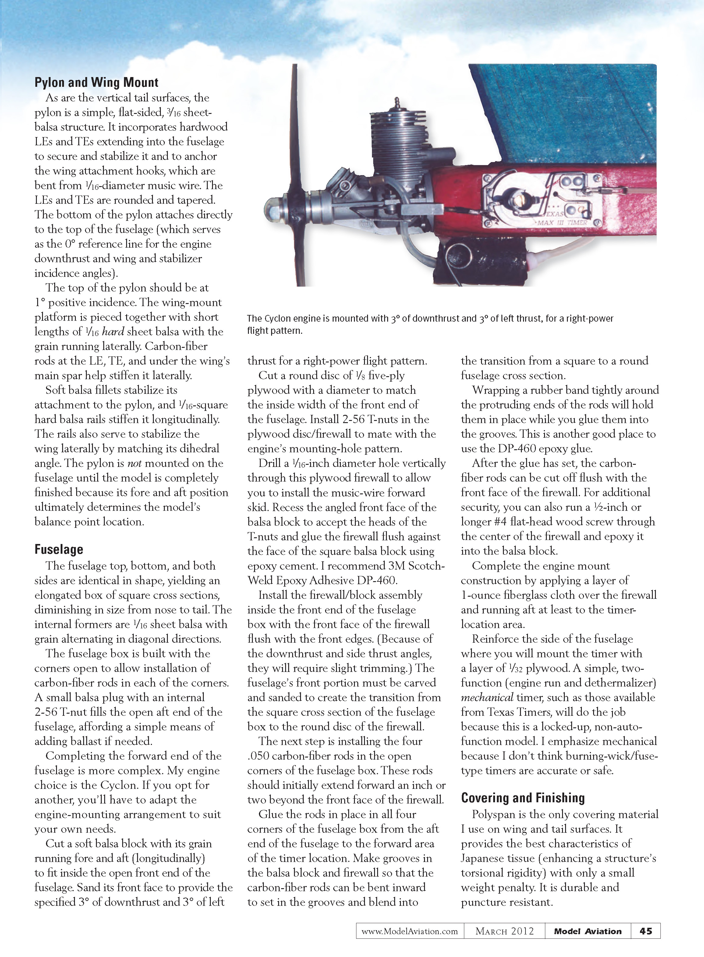
Cut a soft balsa block with its grain running fore and aft (longitudinally) to fit inside the open front end of the fuselage. Sand its front face to provide the specified 3° of downthrust and 3° of left thrust for a right-power flight pattern.
Cut a round disc of 1/8-inch five-ply plywood with a diameter to match the inside width of the front end of the fuselage. Install 2-56 T-nuts in the plywood disc/firewall to mate with the engine’s mounting-hole pattern.
Drill a 1/16-inch diameter hole vertically through this plywood firewall to allow you to install the music-wire forward skid. Recess the angled front face of the balsa block to accept the heads of the T-nuts and glue the firewall flush against the face of the square balsa block using epoxy cement. I recommend 3M Scotch-Weld Epoxy Adhesive DP-460.
Install the firewall/block assembly inside the front end of the fuselage box with the front face of the firewall flush with the front edges. (Because of the downthrust and side thrust angles, they will require slight trimming.) The fuselage’s front portion must be carved and sanded to create the transition from the square cross section of the fuselage box to the round disc of the firewall.
The next step is installing the four .050 carbon-fiber rods in the open corners of the fuselage box. These rods should initially extend forward an inch or two beyond the front face of the firewall.
Glue the rods in place in all four corners of the fuselage box from the aft end of the fuselage to the forward area of the timer location. Make grooves in the balsa block and firewall so that the carbon-fiber rods can be bent inward to set in the grooves and blend into the transition from a square to a round fuselage cross section.
Wrapping a rubber band tightly around the protruding ends of the rods will hold them in place while you glue them into the grooves. This is another good place to use the DP-460 epoxy glue.
After the glue has set, the carbon-fiber rods can be cut off flush with the front face of the firewall. For additional security, you can also run a 1/2-inch or longer #4 flat-head wood screw through the center of the firewall and epoxy it into the balsa block.
Complete the engine mount construction by applying a layer of 1-ounce fiberglass cloth over the firewall and running aft at least to the timer location area.
Reinforce the side of the fuselage where you will mount the timer with a layer of 1/32-inch plywood. A simple, two-function (engine run and dethermalizer) mechanical timer, such as those available from Texas Timers, will do the job because this is a locked-up, non-auto-function model. I emphasize mechanical because I don’t think burning-wick/fuse-type timers are accurate or safe.
Covering and Finishing
Polyspan is the only covering material I use on wing and tail surfaces. It provides the best characteristics of Japanese tissue (enhancing a structure’s torsional rigidity) with only a small weight penalty. It is durable and puncture resistant. Unwanted warps can be removed and trim adjustments made using a heat gun; the surface retains the set you want. Polyspan's only shortcoming is that it only comes in one not-so-vivid color: washed-out white. However, inventive applications of colored tissue, with scarcely any weight penalty, can yield some colorful results.
Apply at least two coats of clear dope, thinned 50%, to all surfaces and edges of the structures that will contact the covering material. Sand lightly after each coat. I prefer to use nitrate dope throughout the entire covering process, with a coat of fuel proofer as the final step.
Polyspan can now be applied and glued to the respective structures' surfaces and edges with thinned dope. The Polyspan does not need to extend forward onto the D-box sheeting more than 1/2 inch. A covering iron set at roughly 300°F will help bend the Polyspan around any small radii such as the wingtips, stabilizer tips, and the stabilizer LE as you apply it.
When complete, heat-shrink the Polyspan with a hot iron to remove wrinkles and tighten the skin. Give all the covered surfaces two coats of 50% thinned, clear nitrate dope.
Now, get artistic with colorful trimming. Applied with thinner, adding colorful Japanese tissue can make your model beautiful and visible against the sky and earth. Apply two coats of 50% thinned dope to all covered and decorated surfaces followed by a final coat of your favorite fuel proofer.
I don't use Polyspan on the all-wood surfaces of the fuselage, pylon and wing mount, fin and rudder, and sub fin. Japanese tissue in your choice of colors and design will do the job. Give the exposed wood surfaces at least two coats of 50% thinned dope with the requisite light sanding afterwards, then apply the tissue using thinned dope. Finish with four more coats of thinned dope and a coat of fuel proofer.
Final Assembly
The final steps include attaching the nose skid, vertical tail and rudder, sub fin, stabilizer platforms, and pylon/wing platform.
Glue the nose skid into the hole in the firewall with DP-460 epoxy after roughening the upper portion's surface with a file or grinding wheel to ensure good glue adhesion. Roughen the upper portion of the tailskid wire and glue it into the hole in the dowel that will support the vertical tail and rudder.
When gluing the sub fin and dowel to the fuselage, take care to ensure that they are vertical and perfectly aligned with its centerline. Position the stabilizer platform as shown on the plans and glue it directly to the top of the fuselage. Glue a small, hard balsa pad to support the stabilizer's TE onto the fuselage top.
After drilling a hole into the vertical tail to accept the protruding support dowel, it can be glued to the top of the fuselage. Proper alignment along the fuselage centerline is critical. The rudder-adjusting mechanism is also installed during this process.
Mount the timer in its fuselage bay and glue short lengths (roughly 2 inches) of 1/16-inch OD aluminum tubing onto the fuselage to act as guides for the DT line. I glue a short length of large-diameter carbon-fiber tubing under the front of the fuselage to hold my bladder-type pressure fuel tank.
Mount the engine to the firewall and the remote fuel cut-off to the engine. Now comes the tricky part—correctly locating the pylon on the fuselage to obtain the desired balance-point location.
The pylon position shown on the plans is intended for heavier, ball-bearing engines such as the Cyclon, A.D., Shuriken, and CS. For lighter, plain-bearing engines (TDs, Stels, VAs, and AMEs), the pylon goes farther aft to attain the desired 85% to 90% balance-point location.
To obtain the correct pylon position, the model must be fully assembled in ready-to-fly condition. In addition to engine, propeller, tank, and timer, you should simulate the weight of the airborne tracker/locator transmitter by taping roughly 4 grams of weight to the TE of the pylon (where the transmitter will be when flying). With the stabilizer in place, you can begin the trial-and-error process of locating the proper pylon position.
Begin by attaching the wing to the top of the fuselage directly behind the engine with rubber bands. Lay the inverted pylon/wing mount (with dummy locator transmitter weight attached) on top of the wing so the forward edge of the wing mount is aligned with the wing’s LE.
Support the whole assembly under each side of the wing at a point three-quarters forward of the wing TE (which will be within the 85% to 90% range). Shifting the wing fore and/or aft, balance the model so that the fuselage is horizontal, determining the correct pylon position.
Measure and mark that place on the top of the fuselage, disassemble all of the components (wing, stabilizer, engine, etc.), and permanently install the pylon on the fuselage in its correct location.
The pylon’s hardwood LE and TE are intended to extend into the fuselage and attach to the balsa block in the front and the fuselage bottom in the back. Cut openings in the fuselage top with the forward one extending down into the balsa block.
Install a 1/16-inch plywood pad 1/2 inch wide inside the fuselage across its width to provide a secure attachment for the pylon’s TE. Cut a slot in one side of the fuselage at the proper location and slide the plywood pad in and glue it in place. Anchor the pylon’s TE with a small wood screw through the pad.
As with the vertical tail and sub fin, aligning the pylon on the fuselage’s centerline is critical. Mount a small tube at the pylon’s TE to hold your transmitter and a couple of small soft balsa blocks to fair/blend its forward end into the pylon-fuselage joint.
Align the wing and stabilizer at right angles to the fuselage centerline each time they are mounted. Short (1/4- to 1/2-inch) lengths of 1/16-inch dowels, split lengthwise and glued to the undersides of the wing LE and TE and stabilizer TE will serve this purpose. (The stabilizer DT horn’s alignment key will do the job at the stabilizer’s LE.) Positioning them on the wing and stabilizer so that they rest against the fuselage sides ensures proper alignment.
Trimming and Testing
Perform all hand-glide and power testing with the airplane in its final flight configuration (propeller, tank, and transmitter installed). I use my own-design propellers, which are available from Mike Hazel (see “Sources”). Constructed from carbon fiber, they come in fixed- and folding-blade versions (blades for the folders are from Mike; hubs for the folders are from me). Their basic size is 6-3/8 x 2 for F1J/.061 use. For 1/2A/.049 use, I cut the diameter to 5-5/8. For more readily available commercial propellers, most fliers use the APC 6 x 2 or 5.7 x 3 or 5.5 x 2.
The Genie Redux is intended to fly a right/right-power/glide flight pattern. Initial hand gliding should ensure a moderate turn with no severe dive or stall tendencies. Adjust the glide turn using stabilizer tilt (right tip up for right turn).
Add ballast to the nose or tail to correct for a stall or dive, respectively. These preliminary adjustments should be considered just that: preliminary. Fine-tune the Genie after the proper power pattern is established.
Engine runs on the first few powered flights should not exceed 3 seconds. Use a short DT setting. The launch angle should be nearly vertical and its direction should be slightly to the right of the wind.
Adjust the power pattern during these initial, short-engine-run test flights by varying the incidence angle of the stabilizer: LE up to correct looping tendencies; TE up to correct diving tendencies.
Experimenting with washin and/or washout on the inboard wing panels is the usual way to correct or induce rolling tendencies. I prefer washin to washout because the drag created by any significant amount of washout can induce a turning effect that overpowers the intended rolling effect.
Conversely, any drag and turning effects from washin tend to work in concert with the intended rolling effect. Progressively increase the engine-run duration by 1-second increments to the maximum (generally 7 seconds at most fields in the East and Midwest). Make concurrent trim adjustments as necessary to attain the desired power pattern of a nearly vertical climb with a three-fourths to full-turn spiral from launch to engine cutoff.
As you become more secure in the power pattern’s safety and perfection, increase the glide duration and observe the glide pattern. The goal is a clockwise circle with a slow, flat, nearly stalled glide attitude. Adjustments to the stabilizer tilt and ballasting to vary the CG are the means to the desired end. Wing washout and/or washin can be used to control the glide’s lateral flatness. Make adjustments in small increments.
Adjusting for glide trim will likely affect power trim. Stabilizer tilt changes may affect decalage, which will probably affect the power pattern. Begin the fine-tuning, tweaking, and compromising to obtain the optimum balance between the powered and gliding flight cycles.
I hope that you will be as satisfied with your Genie Redux as I have been with mine.
—J. G. Pailet F1Cdoug@aol.com
SOURCES:
- Aerospace Composite Products — (800) 811-2009 — www.acpsales.com
- The Composites Store — (800) 338-1278 — www.cstsales.com
- Larry Davidson — (540) 721-4563 — samchamp@charter.net
- Walston Retrieval Systems — (770) 434-4905 — www.walstonretrieval.com
- Mike Hazel — (503) 364-8593 — zzclspeed@aol.com
- Cyclon Engines — (530) 757-6058 — f1cdoug@aol.com
- Texas Timers — (423) 282-6423 — www.texastimers.com
- Campbell’s Custom Kits — (765) 683-1749 — thermalpiglet@yahoo.com
- FAI Model Supply — (570) 882-9873 — www.faimodelsupply.com
Transcribed from original scans by AI. Minor OCR errors may remain.

