
Geophysical: Key Design Elements
By Larry Driskill
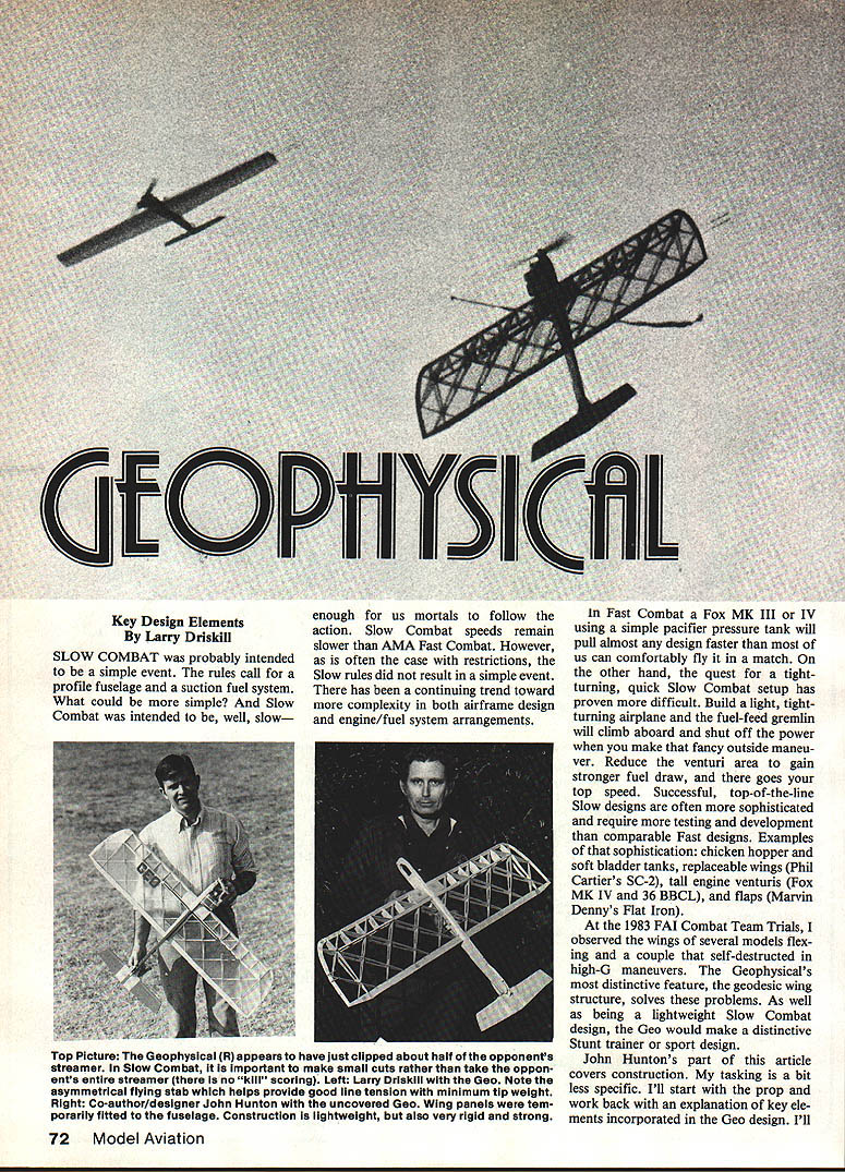
SLOW COMBAT was probably intended to be a simple event. The rules call for a profile fuselage and a suction fuel system. What could be more simple? And Slow Combat was intended to be, well, slow — enough for us mortals to follow the action. Slow Combat speeds remain slower than AMA Fast Combat. However, as is often the case with restrictions, the Slow rules did not result in a simple event. There has been a continuing trend toward more complexity in both airframe design and engine/fuel system arrangements.
In Fast Combat a Fox MK III or IV using a simple pacifier pressure tank will pull almost any design faster than most of us can comfortably fly it in a match. On the other hand, the quest for a tight-turning, quick Slow Combat setup has proven more difficult. Build a light, tight-turning airplane and the fuel-feed gremlin will climb aboard and shut off the power when you make that fancy outside maneuver. Reduce the venturi area to gain stronger fuel draw, and there goes your top speed. Successful, top-of-the-line Slow designs are often more sophisticated and require more testing and development than comparable Fast designs. Examples of that sophistication: chicken hopper and soft bladder tanks, replaceable wings (Phil Cartier's SC-2), tall engine venturis (Fox MK IV and 36 BBCL), and flaps (Marvin Denny's Flat Iron).
At the 1983 FAI Combat Team Trials, I observed the wings of several models flexing and a couple that self-destructed in high-G maneuvers. The Geophysical's most distinctive feature, the geodesic wing structure, solves these problems. As well as being a lightweight Slow Combat design, the Geo would make a distinctive Stunt trainer or sport design.
John Hunton's part of this article covers construction; my tasking is a bit less specific. I'll start with the prop and work back with an explanation of key elements incorporated in the Geo design.
Propellers
Although Combat fliers want to go fast — and Combat is not purely a speed event — I believe a Combat prop should look like a Stunt prop, like a speed prop. A starting point is to try 9 x 6, 9 x 6A, or 9 x 7 medium-blade props.
Engine
The Geophysical was designed for the Fox 36 BBCL MK V. Its long crankshaft allows the engine to be mounted closer to the wing while still complying with the 5-in. nose rule. Besides being readily available and inexpensive, the engine has the advantage of a tall intake stack which helps ensure good fuel draw. Try to stay away from radical timing modifications — they reduce reliability.
Suggested modifications:
- Double-bubble head
- Supertigre needle valve assembly
- General cleanup of ports and passages. With the engine apart, extend the oil groove on the crankshaft journal toward the front case. A few very shallow scratches will help prevent galling and front-end wear.
Fuel system
Two popular ways to go:
- Soft bladder (balloon) tank such as successfully used by Jaden Wooten at the 1981 Nats.
- Chicken-hopper type metal tank such as sold by Triangle Hobbies.
The bladder is lighter and may allow a larger venturi opening; however, I've experienced more consistent performance with metal tanks.
Nose structure
Don't eliminate the 1/4" sq. hardwood spreader that ties the upper and lower engine mounts together. Long noses and heavy engines often suffer vibration problems; a vertical maple spreader helps stiffen the front end.
Spars
Carbon-fiber reinforcement is highly recommended. The weight gain is negligible while strength is greatly increased. I've used both .007-in. sheet and ribbon-type carbon reinforcements.
Center of gravity
Built according to the plans, the Geo will probably come up nose-heavy. The 5-in. nose rule leaves us a choice of a long tail moment or tail weight. I've opted for the tail weight. I use flat sheets of lead that bolt on with a 4-40 bolt and nylon insert nut. This way you can easily adjust the center of gravity (CG) until the airplane is trimmed to suit your flying style.
Bellcrank
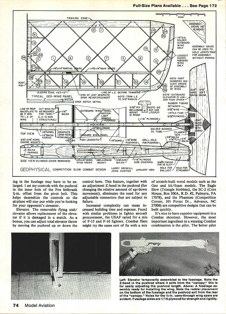
Use a heavy-gauge aluminum bellcrank such as the large Fox. Nylon bellcranks will work, but the opening in the fuselage may have to be enlarged. I set my controls with the pushrod in the inner hole of the Fox bellcrank, 3/8-in. offset from the pivot bolt. This helps desensitize the controls so the airplane will stay put while you're looking for your opponent's streamer.
Elevator
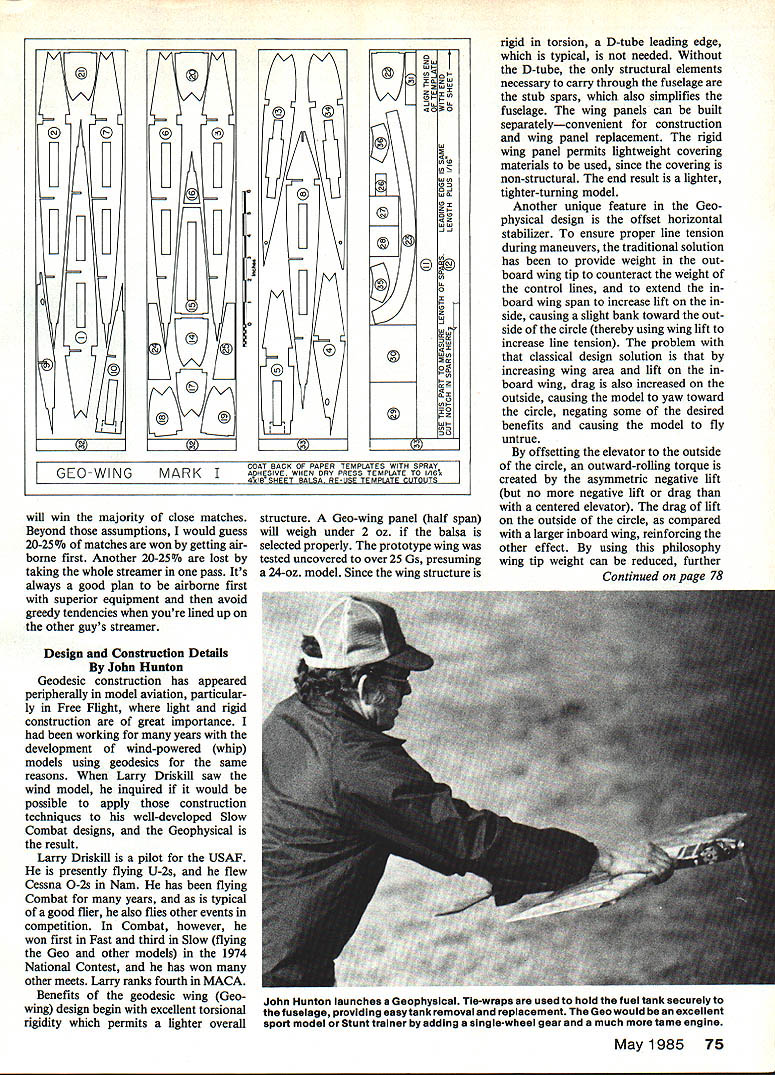
The removable flying stab/elevator allows replacement of the elevator if it is damaged in a match. As a bonus, you can adjust total elevator throw by moving the pushrod up or down the control horn. This feature, together with an adjustment Z-bend in the pushrod (for changing the relative amount of up/down movement), eliminates the need for any adjustable connectors that are subject to failure.
Increased complexity can mean increased building time and expense. Faced with similar problems in fighter aircraft procurement, the USAF opted for a mix of F-15 and F-16 fighters. Combat fliers might try the same sort of fix with a mix of scratch-built wood models such as the Geo and kit/foam models. The Eagle Slow (Triangle Hobbies), the SC-2 (Core House, Box 300A, R.D. #2, Palmyra, PA 17078), and the Phantom (Competition Corner, 101 Forest Dr., Advance, NC 27006) are competitive designs that can be built quickly.
It's nice to have superior equipment in a Combat shootout. However, the most important ingredient in a winning Combat combination is the pilot. The better pilot will win the majority of close matches. Beyond those assumptions, I would guess 20–25% of matches are won by getting airborne first. Another 20–25% are lost by taking the whole streamer in one pass. It's always a good plan to be airborne first with superior equipment and then avoid greedy tendencies when you're lined up on the other guy's streamer.
Design and Construction Details
By John Hunton
Geodesic construction has appeared peripherally in model aviation, particularly in Free Flight, where light and rigid construction are of great importance. I had been working for many years with the development of wind-powered (whip) models using geodesics for the same reasons. When Larry Driskill saw the wind model, he inquired if it would be possible to apply those construction techniques to his well-developed Slow Combat designs, and the Geophysical is the result.
Larry Driskill is a pilot for the USAF. He is presently flying U-2s, and he flew Cessna O-2s in Nam. He has been flying Combat for many years, and as is typical of a good flier, he also flies other events in competition. In Combat, however, he won first in Fast and third in Slow (flying the Geo and other models) in the 1974 National Contest, and he has won many other meets. Larry ranks fourth in MACA.
Benefits of the geodesic wing (Geo-wing) design begin with excellent torsional rigidity which permits a lighter overall structure. A Geo-wing panel (half span) will weigh under 2 oz. if the balsa is selected properly. The prototype wing was tested uncovered to over 25 ozs., presuming a 24-oz. model. Since the wing structure is rigid in torsion, a D-tube leading edge, which is typical, is not needed. Without the D-tube, the only structural elements necessary to carry through the fuselage are the stub spars, which also simplifies the fuselage. The wing panels can be built separately—convenient for construction and wing panel replacement. The rigid wing panel permits lightweight covering materials to be used, since the covering is non-structural. The end result is a lighter, tighter-turning model.
Another unique feature in the Geophysical design is the offset horizontal stabilizer. To ensure proper line tension during maneuvers, the traditional solution has been to provide weight in the outboard wing tip to counteract the weight of the control lines, and to extend the inboard wing span to increase lift on the inside, causing a slight bank toward the outside of the circle (thereby using wing lift to increase line tension). The problem with that classical design solution is that by increasing wing area and lift on the inboard wing, drag is also increased on the outside, causing the model to yaw toward the circle, negating some of the desired benefits and causing the model to fly untrue.
By offsetting the elevator to the outside of the circle, an outward-rolling torque is created by the asymmetric negative lift (but no more negative lift or drag than with a centered elevator). The drag of lift on the outside of the circle, as compared to a larger inboard wing, reinforces the other effect. By using this philosophy wing tip weight can be reduced, further lightening the model.
Building the Geo-wing
The plans include templates for the parts. To build one pair of wing panels, the following materials are required:
- Four sheets of 1/16 x 4 x 36 medium balsa
- Two 1/8 x 4 x 36 hard balsa for the main spars
- Two 1/8 x 4 x 36 hard balsa for the spar doublers
- One 1/8 x 3/16 x 36 soft balsa for the leading edge
- One 1/4 x 3/16 x 18 hardwood for the carry-through spar
- Cyanoacrylate (CYA) glue
- Covering material of your choice
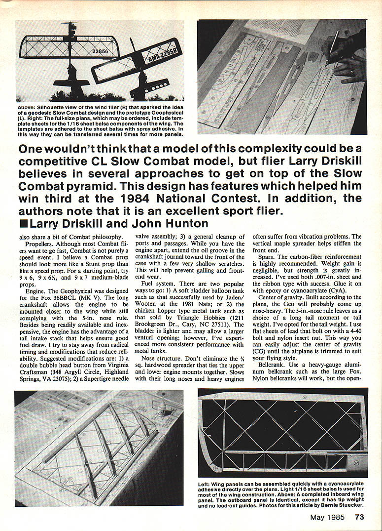
Cut the full-sized templates to the 4-in.-wide strips. Spray the back of the templates with spray adhesive, and let dry. Press the templates to the 1/16 balsa. I suggest you have a second set of balsa sheets handy. As you cut out parts through the templates, transfer the templates to the next sheet of balsa. In this way you can cut out several sheets of parts from one set of templates.
These instructions are based on the use of cyanoacrylate (CYA) glue. Use the thin, quick-curing type for initial assembly, and finish with thick CYA to fill any gaps.
Cut out all parts, being particularly careful to cut all rib slots to accurate width and depth. Cut the 1/4 x 1/4 hard balsa main spars to the same length as the trailing edge parts No. 11 and 12. Notch the spars to mid-depth 5 in. from one end (the 5-in. length of spar will be removed in a later step). Cut the 1/8 x 3/16 soft balsa leading edge 1/16 in. longer than the spars. Cut the four 1/4 x 1/4 partial spars extra long, and trim them later.
Lay the wing plan on a flat work board. Cover the plan with waxed paper, and pin one main spar over the plan with the notch down and toward the root of the wing.
Assemble ribs No. 1, 2, 3, and 4 to the spar with the rib slots up, and tack-glue the ribs to the spar. Add ribs No. 5, 6, 7, 8, and 9 to the assembly without gluing, then slip in rib No. 10. Press the other main spar into place with the notch up and toward the root, and tack-glue it in place.
Block up one trailing edge part No. 11 under the trailing edges of the wing ribs temporarily with the leading edge part. Glue the trailing edge in place. Install the other trailing edge part No. 12, and glue all rib intersections.
Install the first root rib, part No. 13. Attach ribs 5 and 10 to the root rib, then install tip rib parts 14, 15, and 16. Attach the leading edge to ribs 13 and 14, allowing 1/8 in. to project beyond rib 13. Accurately align the root rib with the plan, then attach one diagonal rib to the leading edge.
The wing can now be removed from the bench for final assembly.
Install all of the half-ribs between the spars and leading edge, beginning with part No. 17 near the root and continuing through part No. 22. Now glue the remaining diagonal ribs to the leading edge.
Install tip bow part No. 23 and the tip trailing edge parts No. 24 and 25. Glue part No. 26, the spar spreader, to the root rib—centered on the spar slots.
Enlarge the spar notches in ribs No. 1 and 13, and install the partial spars, tack-gluing them to the ribs and to the portion of the main spar that is to remain. Remove the 5-in. portion of the main spars.
Install spar gusset parts No. 27 and 28, the sheeting parts No. 29 and 30, and root rib brace part No. 31. Add root sheet parts No. 32 and 33, trimming as required.
Sand the root rib flat with a block sander, except for the projecting leading edge, and glue on root rib part No. 34 at the root. Add the tip reinforcing parts No. 35 and 36. Go over all joints with CYA glue.
Shape the leading edge to a full-round 1/4-in. radius, and sand the entire wing smooth with a long sanding block. Trim out the lead-outs at the root rib. Install the lead-out guides in the inboard wing, and tip weight in the outboard panel. Cover the wing.
Wing pairs should be built opposite hand (build one from the front of the plans, one from the back) to ensure geometric symmetry.
Fuselage and tail
Basic material list:
- One 3/8 x 3/8 x 36 medium engine bearer
- One 1/8 x 3/8 x 36 medium balsa longerons
- One 1/8 x 2 x 24 plywood fuselage filler
- Two 1/8 x 2 x 24 plywood fuselage sides
- One 1/8 x 2 x 12 plywood sheet for crank mounts and fin
- One 1/8 x 2 x 12 medium balsa for nose fairing
- One 4 in. x 1/2 in. O.D. brass tube with slip-fit music wire 5 in. long
- One 1/8 x 6 in. dowel stock
- Fuelproof finishing materials of your choice
- Engine and fuel tank
- Sturdy bellcrank and 1/8 in. music wire pushrod
Gluing of the fuselage parts can be accomplished economically by using white glue (aliphatic resin) to provide the structural bond, and CYA through the white glue to speed assembly. After applying a thin coat of white glue to both sides of a joint, apply spots of CYA, then clamp the parts firmly. The joint will bond very quickly.
Cut the 3/8 balsa fuselage filler to shape, then the longerons and engine mounts. Assemble the engine mounts and longerons to the filler. Check the fit of the engine, and add the hardwood spreader, cutting it to accurate length.
Cut out a 3/8 balsa tail block. Pull the longerons to it, and glue the joints. Cut the 1/8 balsa longeron spreaders to length. Drill for the pushrod, and install it. Install the balsa fairings ahead of the engine mounts.
Sand and shape the fuselage, then add the fin and stabilizer parts. The fin should be mounted in a slot.
Install the bellcrank mounting plates. Install the 1/8 hardwood dowels at the engine mount crosspiece and on the bellcrank mounting plate to limit bellcrank travel, and for the rear wing pin.
Cut the elevator parts to shape, then join them. Sand the elevator to a smooth airfoil shape. Apply light glass cloth to the center section of the elevator with CYA. Install the hinge tubes with epoxy, using filament tape for reinforcing.
Finish the fuselage and elevator assemblies with a fuel-proof system. Make every effort to keep the nose light, since tail weight will probably have to be added to make the model balance properly.
Install the bellcrank and 0.021 lead-outs. Lead-outs can be fished through the wing with a piece of wire. Install the elevator and elevator horn. Joggle the rear end of the pushrod with an extra jog for fine adjustment.
Install the engine and fuel system.
Cut the hardwood stub spars to length, and slide them into the fuselage. Pre-fit the wings. If you can get carbon-fiber material, slide a 1/4-in.-wide piece over the stub spar to extend 3 in. onto each main wing spar. Use CYA for anchoring the carbon-fiber and wings to the fuselage. If the carbon-fiber material is not available, coat all joining surfaces with epoxy, and assemble the wings.
Balance the model with the center of gravity approximately 3/8 in. ahead of the center of the main spar. You can make the controls more responsive by adding weight to the tail and moving the CG rearward in small increments.
The Geophysical is light and responsive. If your flying skills are rusty, or if you are building it as a sport-stunt trainer, begin with the CG well forward for slower control response. In Combat trim, in the hands of an experienced flier like Larry Driskill, the Geophysical is awesome.
Transcribed from original scans by AI. Minor OCR errors may remain.

