
Gimlet40
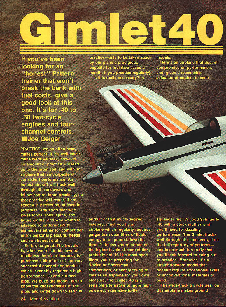
If you've been looking for an "honest" pattern trainer that won't break the bank with fuel costs, give a good look at this one. It's for .40 to .50 two-cycle engines and four-channel controls. — Joe Geiger
Practice, we so often hear, makes perfect. If it's well-made maneuvers we seek, however, no amount of practice will lead us to the promised land with an airplane that isn't capable of consistent performance. An honest aircraft will track well through all maneuvers and follow control input precisely, so that practice will result, if not exactly in perfection, at least in progress. Any sport flier who loves loops, rolls, spins, and figure eights, and who wants to advance to pattern-quality maneuvers either for competition or for personal pleasure, needs such an honest craft.
When reaching this level of readiness there's a tendency to purchase a kit of one of the very successful competition models — which invariably requires a high-performance .60 and a tuned pipe. Must you fly an airplane which regularly requires gargantuan quantities of fuel? Unless you're at one of the higher levels of competition, probably not. If, like most sport fliers, you're preparing for Novice or Sportsman competition, or simply trying to master an airplane for your own pleasure, the Gimlet .40 is a sensible alternative to more high-powered, expensive-to-fly models.
The Gimlet doesn't compromise on performance and, given a reasonable engine selection, doesn't squander fuel. A good Schnuerle .40 with a stock muffler is all you'll need for dazzling performance. The Gimlet tracks well through all maneuvers, does the full repertory of patterns—and is so much fun to fly that you'll look forward to practice. Moreover, it's a straightforward model that doesn't require exceptional skills or unconventional materials to build.
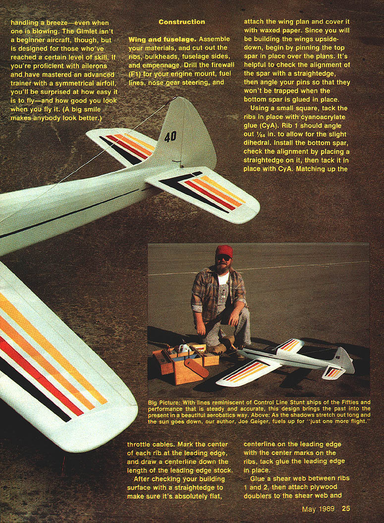
The wide-track tricycle gear makes ground handling a breeze—even when one is blowing. The Gimlet isn't a beginner aircraft, though; it is designed for those who've reached a certain level of skill. If you're proficient with ailerons and have mastered an advanced trainer with a symmetrical airfoil, you'll be surprised at how easy it is to fly—and how good you look when you fly it.
Construction
Wing
- Assemble materials and cut out ribs, spars, leading and trailing edges, and other wing parts. Mark the center of each rib at the leading edge and draw a centerline along the length of the leading-edge stock.
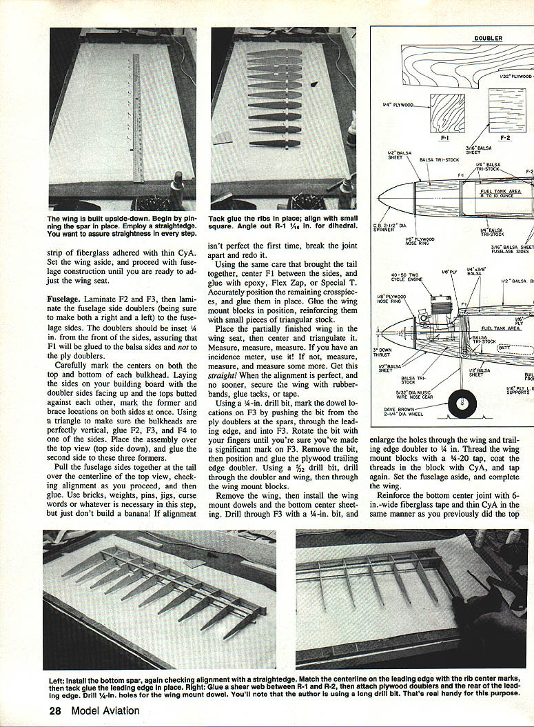
- Check your building surface with a straightedge to make sure it is perfectly flat. Cover the plans with waxed paper and build the wing upside-down.
- Pin the top spar in place over the plans. Check alignment with a straightedge and angle pins so they won't be trapped when gluing the bottom spar.
- Tack the ribs in place with cyanoacrylate (CyA) using a small square. Rib 1 should angle out 1/64 in. to allow for slight dihedral.
- Install the bottom spar, check alignment with a straightedge, and tack in place with CyA. Match the centerline on the leading edge to the center marks on the ribs and tack the leading edge in place.
- Glue a shear web between ribs 1 and 2; attach plywood doublers to the shear web and to the rear of the leading edge.
- Drill 1/4-in. holes for the wing-mount dowel using a long drill bit, but do not install the dowel yet.
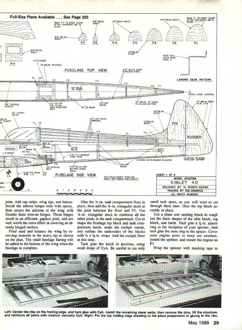
- Center each rib on the 1/4-in. trailing-edge stock and tack with CyA. Install the remaining shear webs with the grain running vertical.
- Remove pins, lift the structure, and reinforce all joints with medium-strength CyA. A kicker (e.g., Hot Shot) speeds the process.
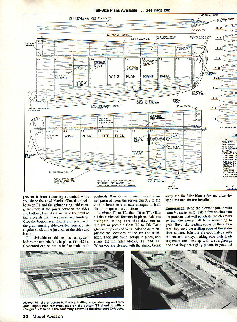
- Pin the top trailing-edge sheeting over the plan, then pin the wing structure on top and glue with CyA. When fully set, remove pins and glue the bottom trailing-edge sheeting with slow-setting CyA.
- Use a 30-in. straight 1x2 to hold the assembly flat while the CyA sets; hold for a timed two minutes to ensure a perfectly straight trailing edge.
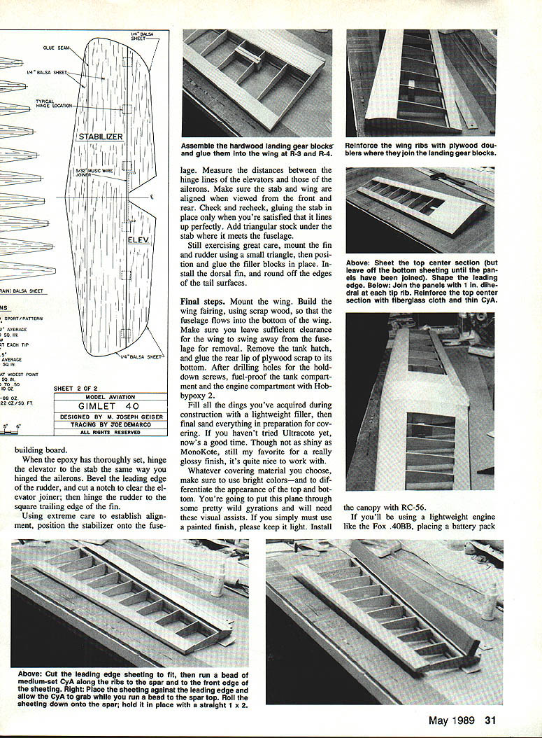
- Cut the leading-edge sheeting to fit. Run a bead of medium CyA on the tops of the ribs from the leading edge to the spar and along the front edge of the sheeting. Place the front edge against the rear of the leading edge, run another bead along the top spar, then roll the sheeting down onto the spar. Hold with the straight 1x2 until set. Repeat for the other wing.
- Assemble and glue landing-gear blocks in place; reinforce ribs with plywood doublers where they join the blocks.
- Sheet the top center section of the wing but leave the bottom center sheeting off until the wings are joined and the dowel holes have been located in F3.
- Shape the leading edge and build the other wing to the same point. Join the wings with 1 in. dihedral at each tip rib. When the wing joint is secure, reinforce the top center area with a 6-in.-wide plywood cap.
- For additional reinforcement, a strip of fiberglass adhered with thin CyA may be used. Set the wing aside until ready to adjust the wing seat.
- Add cap strips, wing tips, and braces. Install the aileron torque rods with epoxy and secure the ailerons to the wing with Granite State iron-on gapless hinges for an efficient, gapless joint.
- Final sand and balance the wing by removing material in the heavy tip as shown on the plan. Add the small fuselage fairing to the bottom of the wing when the fuselage is complete.
Fuselage
- Laminate F2 and F3. Laminate fuselage side doublers and make both right and left doublers. The doublers should inset 1/4 in. from the front of the sides so F1 will glue to the balsa sides rather than to the ply doublers.
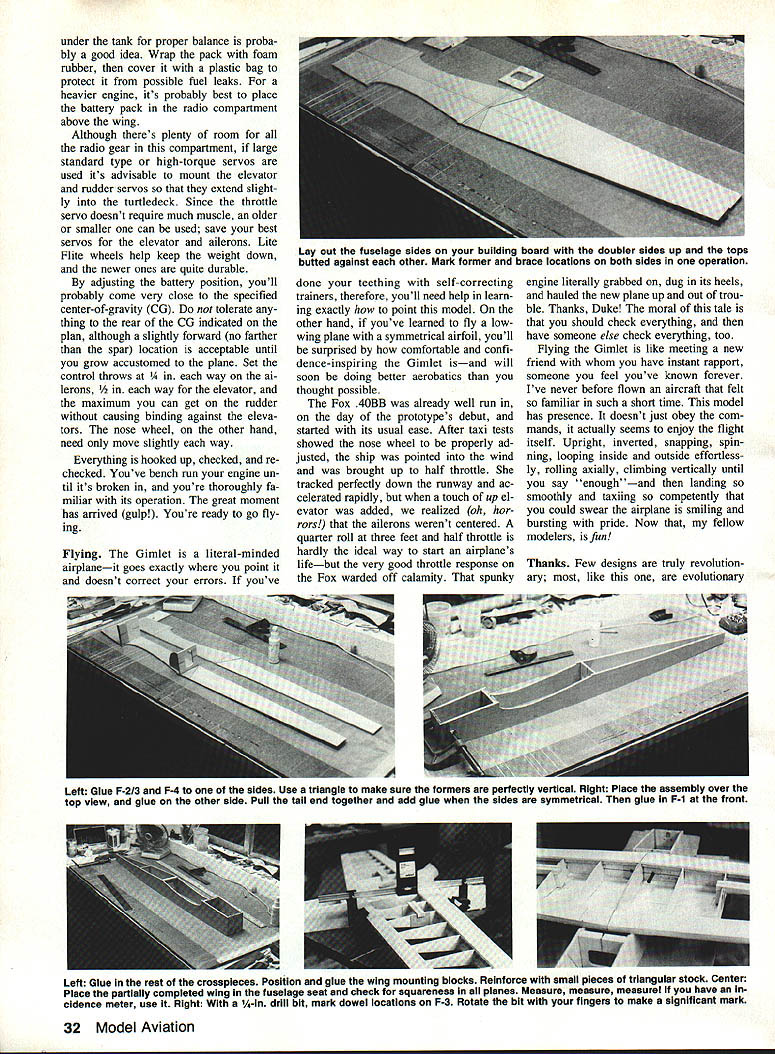
- Carefully mark the centers on both the top and bottom of each bulkhead. Lay the sides on the building board with the doubler sides facing up and the tops butted against each other; mark former and brace locations on both sides at once.
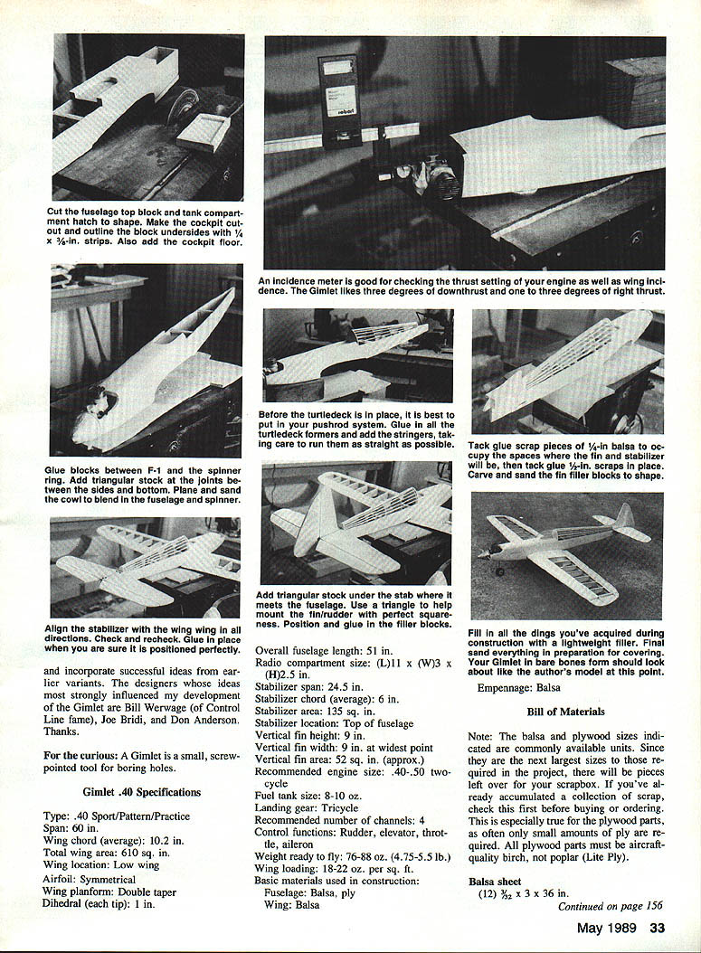
- Using a triangle to ensure bulkheads are perfectly vertical, glue F2, F3, and F4 to one of the sides. Place the assembly over the top view (top side down) and glue the second side to these formers.
- Pull the fuselage sides together at the tail over the centerline of the top view, check alignment, and glue. Use bricks, weights, pins, jigs—or whatever is necessary—but don't build a banana. If alignment isn't perfect, break the joint apart and redo it.
- Center F1 between the sides and glue it with epoxy (Flex, Zap, or Special T). Accurately position remaining crosspieces and glue them in place.
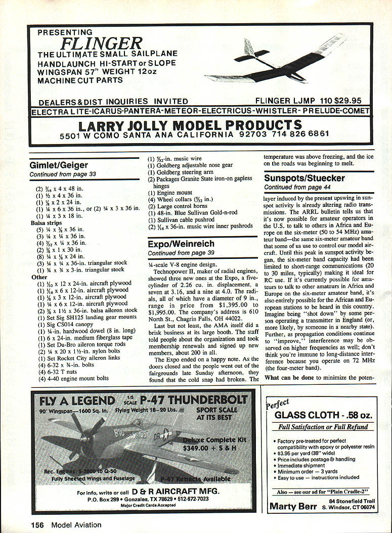
- Glue the wing-mount blocks in position and reinforce them with small pieces of triangular stock.
- Place the partially finished wing in the wing seat, then center and triangulate it. Measure frequently; use an incidence meter if available. Get the straight alignment perfect before securing the wing with rubber bands, glue tacks, or tape.
- Using a 1/4-in. drill bit, mark the dowel locations on F3 by pushing the bit through the ply doublers and spars at the leading edge and into F3. Rotate the bit with your fingers until you make a clear mark on F3. Remove the bit and position and glue the plywood trailing-edge doubler.
- Using a 5/32-in. drill bit, drill through the doubler and wing, then through the wing-mount blocks. Remove the wing, install the wing-mount dowels, and install the bottom center sheeting.
- Drill through F3 with a 1/4-in. bit and enlarge the holes through the wing and trailing-edge doubler to 1/4 in. Thread the wing-mount blocks with a 1/4-20 tap, coat the threads in the block with CyA, and tap again.
- Reinforce the bottom center joint with 6-in.-wide fiberglass tape and thin CyA as done for the top.
- Glue the 1/2-in. tank compartment floor in place, then add 3/8-in. triangular stock as the joint between the floor and F1. Use 1/4-in. triangular stock to reinforce other joints in the tank compartment.
- Cut and shape the fuselage top block and tank compartment hatch. Make the cockpit cutout and outline the undersides of the blocks with 1/4 x 3/8-in. strips. Add the cockpit floor.
- Tack-glue the hatch in position with small drops of CyA; use only small tack spots so the hatch can be cut free later. Glue the top block securely in place.
- Rough out the basic shapes of the chin block, top block, and hatch with a plane and sanding block. Tack-glue a 1/8-in. spacer ring to the backplate of your spinner, then tack-glue the nose ring to the spacer. Cover engine ports to keep out sawdust; mount the spinner and engine on F1.
- Wrap the spinner with masking tape to prevent scratching while shaping the cowl blocks. Glue the blocks between F1 and the spinner ring, add triangular stock at the joints between the sides and bottom, then plane and sand the cowl so it blends with the spinner and fuselage.
- Glue the bottom rear sheeting in place with the grain running side-to-side, then add triangular stock at the junction of the sides and bottom.
Pushrods, Turtledeck, and Tail
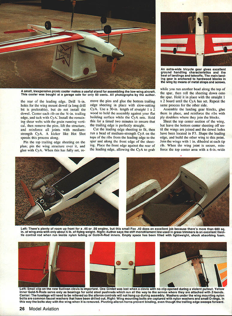
- Install the pushrod system before the turtledeck is in place. One 48-in. Goldenrod can be cut in half to make both pushrods. Run 1/16-in. music wire inside the inner pushrod from the servos directly to the control horns to reduce trim changes due to temperature.
- Laminate T1 to T2, then T6 to T7. Glue all turtledeck formers in place.
- Add stringers, taking care they run straight from T2 to T6. Tack-glue scrap 1/8-in. balsa to duplicate the locations of the fin and stabilizer and tack-glue 1/2-in. scraps in place. Shape the thin filler blocks, T1, and T7; when satisfied, break away the thin filler blocks for later use after stabilizer and fin installation.
Empennage
- Bend the elevator joiner wire from 5/32-in. music wire. File a few notches into the portions that penetrate the elevators so the epoxy will have something to grab.
- Bevel the leading edges of the elevators but leave the stabilizer trailing edge square. Join the elevator halves with epoxy, making sure their leading edges are lined up with a straightedge and they are tightly pinned to a flat board.
- When the epoxy has set, hinge the elevator to the stabilizer as you did the ailerons.
- Bevel the leading edge of the rudder and cut a notch to clear the elevator joiner; hinge the rudder to the square trailing edge of the fin.
- Carefully establish alignment when positioning the stabilizer onto the fuselage. Measure distances between the hinge lines of the elevators and those of the ailerons. Make sure the stabilizer and wing are aligned when viewed from front and rear. Glue the stabilizer in place only when perfectly satisfied with alignment. Add triangular stock under the stabilizer where it meets the fuselage.
- Mount the fin and rudder using a small triangle and position and glue filler blocks in place. Install the dorsal fin and round off tail-surface edges.
Final steps
- Mount the wing. Build the wing fairing from scrap wood so the fuselage flows into the bottom of the wing but leave sufficient clearance for wing removal.
- Remove the tank hatch and glue a rear lip of plywood scrap to its bottom. Drill holes for the hold-down screws and fuel-proof the tank and engine compartments with Hobbypoxy 2.
- Fill dings from construction with lightweight filler and final-sand in preparation for covering. Ultracote is recommended for a glossy finish, though MonoKote is an alternative.
- Use bright, contrasting colors and differentiate the appearance of the top and bottom—these visual assists help during aerobatics. If using paint, keep it light. Install the canopy with RC-56.
- Battery placement:
- For a lightweight engine (e.g., Fox .40BB), place a battery pack under the tank for proper balance. Wrap the pack with foam rubber and cover with a plastic bag to protect from possible fuel leaks.
- For a heavier engine, locate the battery pack in the radio compartment above the wing.
- Radio gear: although there's ample room in the radio compartment, if using large standard or high-torque servos it is advisable to mount elevator and rudder servos so they extend slightly into the turtledeck. Throttle servo requires less power; save the best servos for elevator and ailerons.
- Wheels: Lite Flite wheels help keep weight down; newer ones are durable.
- Balance (CG): by adjusting battery position you should come close to the plan's specified center of gravity (CG). Do not tolerate a CG rear of the indicated point; a slightly forward CG (no farther than the spar) is acceptable at first.
- Control throws: set ailerons 1/4 in. each way, elevator 1/2 in. each way, and rudder to the maximum without binding against the elevators. Nose wheel needs only slight movement either way.
- Preflight: hook everything up and re-check. Bench-run the engine until broken in and thoroughly familiar with its operation.
Flying notes
- The Gimlet is literal-minded—it goes exactly where you point it and doesn't correct your errors. Pilots who learned on self-correcting trainers will need help transitioning to this type of model; those experienced with low-wing, symmetrical-airfoil planes will find it comfortable and confidence-inspiring.
- On the prototype's debut, ailerons were found off-center during takeoff testing. A well-run-in Fox .40BB delivered excellent throttle response and helped recover the flight. Moral: check everything, and have someone else check everything, too.
- The Gimlet performs upright, inverted, snapping, spinning, looping inside and outside, and effortless aileron rolls. It climbs vertically and lands smoothly—an airplane that is rewarding and fun.
Thanks and acknowledgments
- Few designs are truly revolutionary; most are evolutionary. I incorporated successful ideas from earlier variants. The designers who most strongly influenced my development of the Gimlet are Bill Weverange (of control-line fame), Joe Bridi, and Don Anderson.
- For the curious: a gimlet is a small, screw-pointed tool for boring holes.
Gimlet .40 Specifications
- Type: .40 Sport / Pattern / Practice
- Recommended engine size: .40–.50 two-cycle
- Fuel tank size: 8–10 oz.
- Recommended number of channels: 4
- Control functions: rudder, elevator, throttle, aileron
- Span: 60 in.
- Wing chord (average): 10.2 in.
- Total wing area: 610 sq. in.
- Wing location: Low wing
- Airfoil: Symmetrical
- Wing planform: Double taper
- Dihedral (each tip): 1 in.
- Overall fuselage length: 51 in.
- Radio compartment size: L 11 x W 3 x H 2.5 in.
- Stabilizer span: 24.5 in.
- Stabilizer chord (average): 6 in.
- Stabilizer area: 135 sq. in.
- Stabilizer location: Top of fuselage
- Vertical fin height: 9 in.
- Vertical fin width: 9 in. at widest point
- Vertical fin area: ≈ 52 sq. in.
- Landing gear: Tricycle
- Weight ready to fly: 76–88 oz. (4.75–5.5 lb.)
- Wing loading: 18–22 oz. per sq. ft.
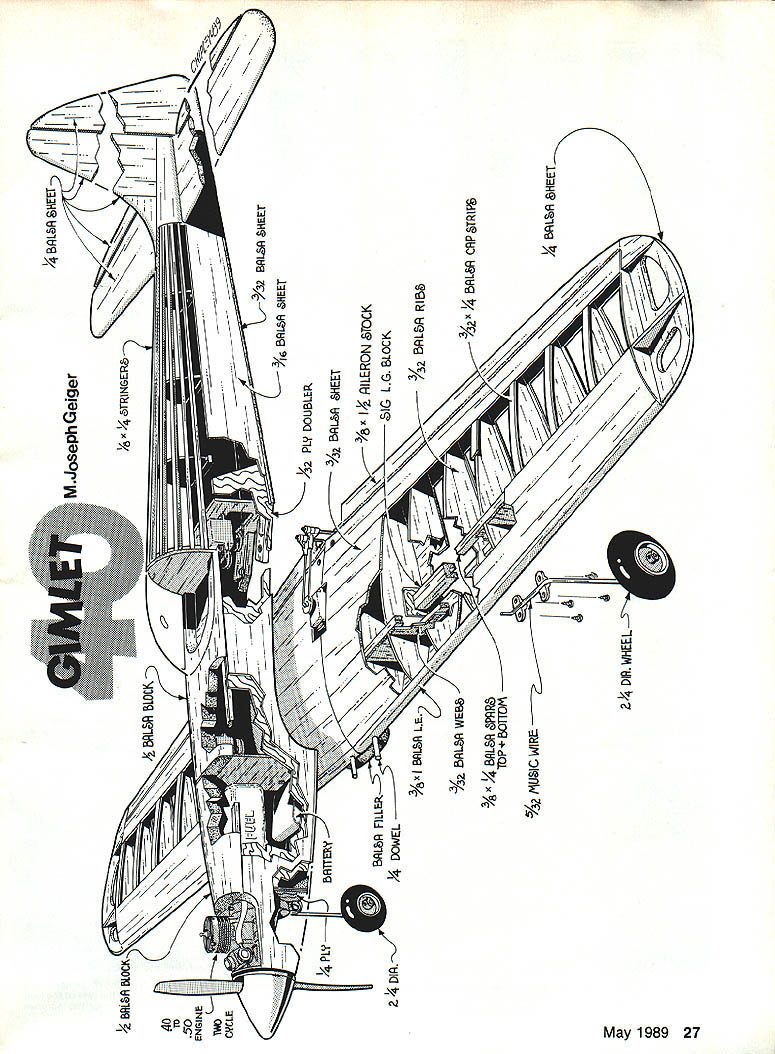
- Basic materials:
- Fuselage: balsa, plywood
- Wing: balsa
Bill of Materials
Note: Balsa and plywood sizes listed are commonly available units; you may have leftovers for the scrapbox. All plywood parts must be aircraft-quality birch (Lite Ply), not poplar.
Balsa sheet
- (12) 3/32 x 3 x 36 in.
- (2) 3/16 x 4 x 48 in.
- (1) 1/2 x 4 x 36 in.
- (1) 1/2 x 2 x 24 in.
- (1) 1/4 x 6 x 36 in., or (2) 1/4 x 3 x 36 in.
- (1) 1/4 x 3 x 18 in.
Balsa strips
- (5) 1/8 x 3/8 x 36 in.
- (3) 1/8 x 1/2 x 36 in.
- (4) 1/8 x 1/4 x 30 in.
- (2) 1/4 x 1/2 x 36 in.
- (3) 1/4 x 1 x 24 in.
- (3) 1/4 x 3 x 36-in. triangular stock
- (1) 3/8 x 3 x 3-in. triangular stock
Other
- (1) 1/8 x 12 x 24 in. aircraft plywood
- (1) 1/16 x 6 x 12 in. aircraft plywood
- (1) 1/16 x 3 x 12 in. aircraft plywood
- (1) 1/4 x 6 x 12 in. aircraft plywood
- (2) 3/32 x 1 1/2 x 36-in. balsa aileron stock
- (1) Set Sig SH125 landing gear mounts
- (1) Sig CS014 canopy
- (1) 1/4-in. hardwood dowel (8 in. long)
- (1) 6 x 24-in. medium fiberglass tape
- (1) Set Du-Bro aileron torque rods
- (2) 1/4 x 20 x 1 1/2-in. nylon bolts
- (1) Set Rocket City aileron links
- (4) 6-32 x 3/8-in. bolts
- (4) 6-32 T-nuts
- (4) 4-40 engine mount bolts
- (1) 5/32-in. music wire
- (1) Goldberg adjustable nose gear
- (1) Goldberg steering arm
- (2) Packages Granite State iron-on gapless hinges
- (1) Engine mount
- (4) Wheel collars (5/32 in.)
- (2) Large control horns
- (1) 48-in. Blue Sullivan Gold-n-rod
- (1) Sullivan cable pushrod
- (2) 1/16 x 36-in. music wire inner pushrods
Transcribed from original scans by AI. Minor OCR errors may remain.

