
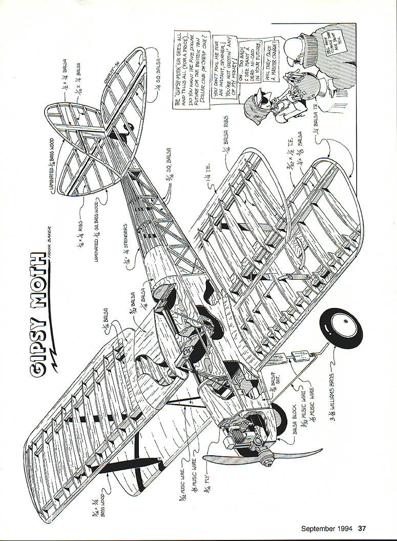
Gipsy Moth
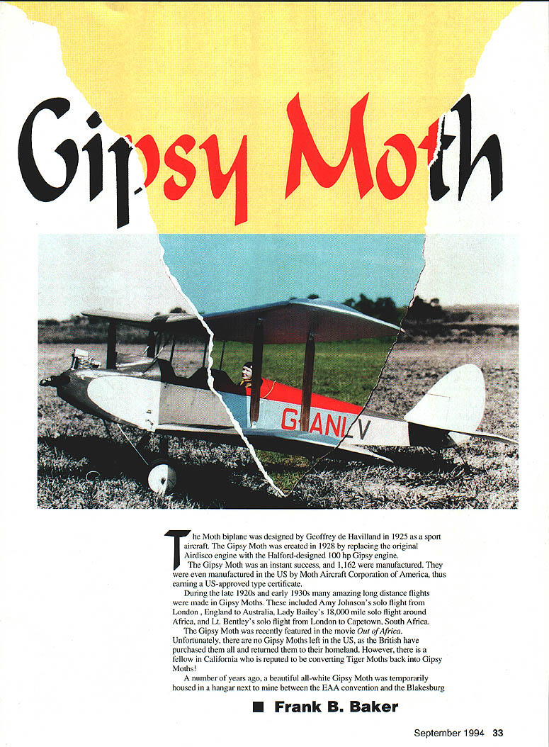
The Moth biplane was designed by Geoffrey de Havilland in 1925 as a sport aircraft. The Gipsy Moth was created in 1928 by replacing the original Airdisco engine with the Halford-designed 100 hp Gipsy engine.
The Gipsy Moth was an instant success; 1,162 were manufactured. They were even produced in the U.S. by Moth Aircraft Corporation of America, earning a U.S.-approved type certificate.
During the late 1920s and early 1930s many notable long-distance flights were made in Gipsy Moths, including Amy Johnson's solo flight from London to Australia, Lady Bailey's 18,000-mile solo flight around Africa, and Lt. Bentley's solo flight from London to Cape Town, South Africa.
The Gipsy Moth was recently featured in the movie Out of Africa.
There are no Gipsy Moths left in the U.S.; most have been repatriated to Britain. However, enthusiasts continue to restore and convert related types.
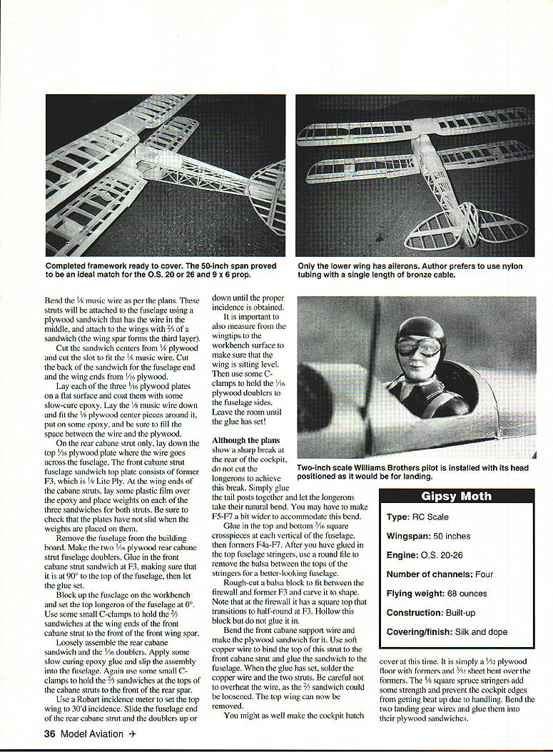
A small, fragile 50-inch model Gipsy Moth described here was developed after studying three-view drawings from Aeromodeller and selecting an OS 20 four-stroke (later replaced by the OS 26 Surpass). The model was matched to a 9 x 6 prop and built as a moderately sized, realistic flying scale model.
Construction
The model is light and weight-conscious construction is important. Use epoxy sparingly and choose appropriate balsa densities for each part to keep weight down.
Materials and general notes
- Keep epoxy use minimal; it adds weight quickly.
- Select balsa of the correct hardness/density for each use.
- Build wings first so the fuselage can be started while wings dry.
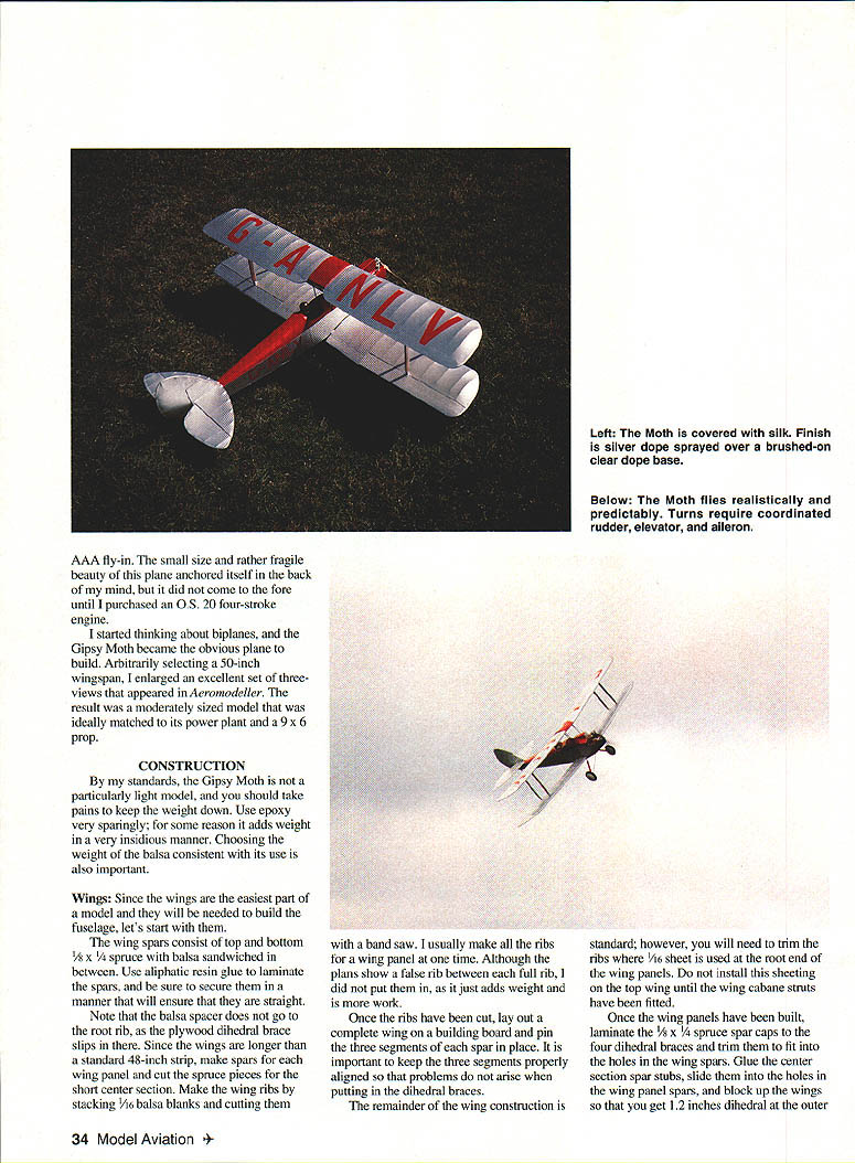
- The Moth is traditionally covered with silk; finish with clear dope and silver spray.
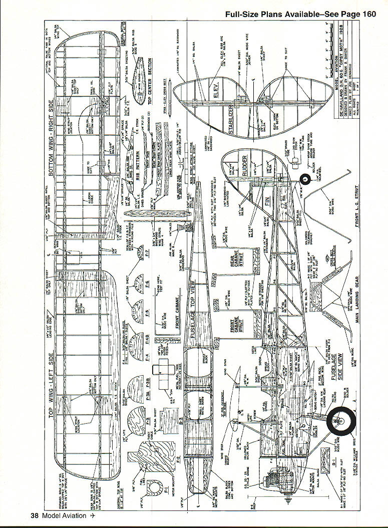
Wings
- Wingspan selected: 50 inches (model).
- Spars: top and bottom 1/8 x 3/8 balsa sandwiched between 1/32 plywood; laminate with aliphatic resin glue and ensure straight alignment.
- Because wings exceed standard 48-inch stock, make spars in two wing-panel pieces and cut short spruce pieces for the center section.
- Ribs: stack 1/16-inch balsa blanks (or 3/16 in other references) and cut on a bandsaw; make ribs for each panel at one time. False ribs shown on plans may be omitted to save weight.
- Pin the complete wing on the building board, aligning the three-segment spar carefully to avoid dihedral/twist problems.
- Sheet the root ends with 1/16-inch sheet where indicated. Do not install top-wing sheeting until cabane struts are fitted.
- Dihedral and center section:
- Laminate 1/8 x 3/8 spar caps and fit the four dihedral braces.
- Glue center-section spar stubs into the wing-panel spar holes and block up the wings to obtain 1-1/2 inches dihedral per outer panel (check plans for exact measurement).
- After checking for equal dihedral and no twist, let glue cure overnight.
- Cut and glue 1/8-inch plywood dihedral plates cambered to the front and rear of the spar at the center, using a razor saw to cut rib slots if required.
- Split eight 3/32 balsa center ribs lengthwise and glue to the center section top; top center section is sheeted to provide a hand-hold. Lower wing has no center-section ribs; lower wing spars glue directly to the fuselage.
- Ailerons: located on the lower wing.
- Preferred actuation: continuous aileron cable with a Z-piece soldered in the center to hook onto the servo arm, with nylon tubing over the cable for guide/turns.
- Bring nylon tubing forward per plans with smooth, large-radius turns; abrupt 90° bends will harm operation.
- Install tubing over cable until lower wing is glued to fuselage; cable runs inside tubing thereafter.
- Wing-strut supports:
- Cut eight outer wing-strut supports from .015-inch aluminum sheet; bend per plans and drill bolt holes.
- Bind strut supports to wing spars with soft copper wire; top strut fittings should point down and bottom fittings point up.
- Coat wire fittings with Ambroid glue.
- Cut slits in 1/16-inch sheeting to go over fittings and glue sheets between appropriate ribs to anchor the covering and area brackets.
- Result: about 5/8 inch of metal exposed for the fittings/attachment and a tidy, strong connection.
Fuselage
- Build two fuselage sides directly over plans.
- Use the hardest available 3/16-inch square balsa for top and bottom longerons.
- Do not install 3/8-inch sheet triangles at the rear of the cockpit until sides are joined.
- Glue a 1/2-inch plywood doubler to the inside of each fuselage side with epoxy.
- Firewall and engine mount:
- Make a 3/16-inch plywood firewall and cut holes for engine mounts (do not drill gas tank holes until tank fitted).
- Glue maple engine mount beams into the firewall with epoxy, using metal triangles to ensure beams are square and have no down or side thrust.
- Epoxy 1/8-inch plywood front beam former in place.
- Assembly:
- Lay both fuselage sides top down on a flat surface with ~1/4 inch front overhang; pin and block straight and even.
- Glue in 1/8-inch square top and bottom crosspieces where former F4 will go, then glue former B3 and the 3/16-inch sheet (grain crosswise) from B3 to the 3/16-inch square crosspiece.
- Do not glue tail posts together at this stage.
- Fuel tank (recommended homemade tank):
- Construct from K & S #254 easy-solder tin sheet using full-size patterns.
- Solder tank with rear left open initially. Make three tubes from 1/8-inch copper tubing: two vents and one fuel line.
- Run fuel line to the bottom center rear of the tank and solder; ensure tube remains open.
- Bring all three tubes straight out the front of the tank and solder both inside and outside.
- Close and solder rear, clean off soldering paste with solvent, then pressure-test in water for leaks.
- Drill firewall holes for the three tubes; slip tubes partially through firewall, epoxy tank to firewall and push forward to set.
- Bend center fuel line upward and trim leaving about 1/2 inch of straight tubing for carburetor connection.
- Epoxy firewall assembly to fuselage, ensuring zero down or side thrust. Glue 3/16-inch sheet tank support under tank.
- Cockpit hatch and nose block:
- Make cockpit hatch cover from 1/32-inch plywood over formers with 3/32-inch sheet bent over formers; reinforce with 1/8-inch square spruce stringers.
- Rough-cut a balsa block to fit between firewall and former F3, carve to shape (square top at firewall transitioning to half-round at F3), hollow it out, but don’t glue in yet.
- Landing gear:
- Bend two landing gear wires and glue them into plywood sandwiches.
- Clamp plywood sandwich for forward 3/32-inch music wire landing gear to back of fuselage during final assembly.
- Epoxy landing gear sandwich to rear of firewall, wrap wires with copper and solder supports to main gear wire.
- Solder two strips of 1/4-inch-wide brass shim stock to each main landing gear leg and glue on airfoil-shaped balsa fairleads.
- Glue in 3/16-inch sheet cross-grain from firewall to main landing gear sandwich.
Cabane struts and top-wing mounts
- Bend 1/8-inch music wire as per plans for cabane struts.
- Cabane strut attachment is a plywood sandwich with wire in the middle:
- Center pieces cut from 1/8-inch plywood with slot for 1/8-inch music wire.
- Top and bottom plates cut from 1/16-inch plywood.
- Assembly:
- Coat three 1/16 plates with slow-cure epoxy, lay the 1/8 wire, fit the 1/8 plywood centers around wire, fill with epoxy and clamp with weights.
- For the rear cabane only, include the top 1/16 plate where the wire crosses the fuselage; the front top plate is former F3 (Lite Ply).
- Make two 1/8 plywood rear cabane strut fuselage doublers.
- Glue the front cabane strut sandwich at F3 at 90° to the top of fuselage.
- Block the fuselage so top longeron sits at 0°. Use C-clamps to hold the 1/8 sandwiches at wing ends to the front of the front wing spar.
- Assemble rear cabane sandwich loosely with doublers, epoxy in place and clamp the 3/32 sandwiches to front of rear spar.
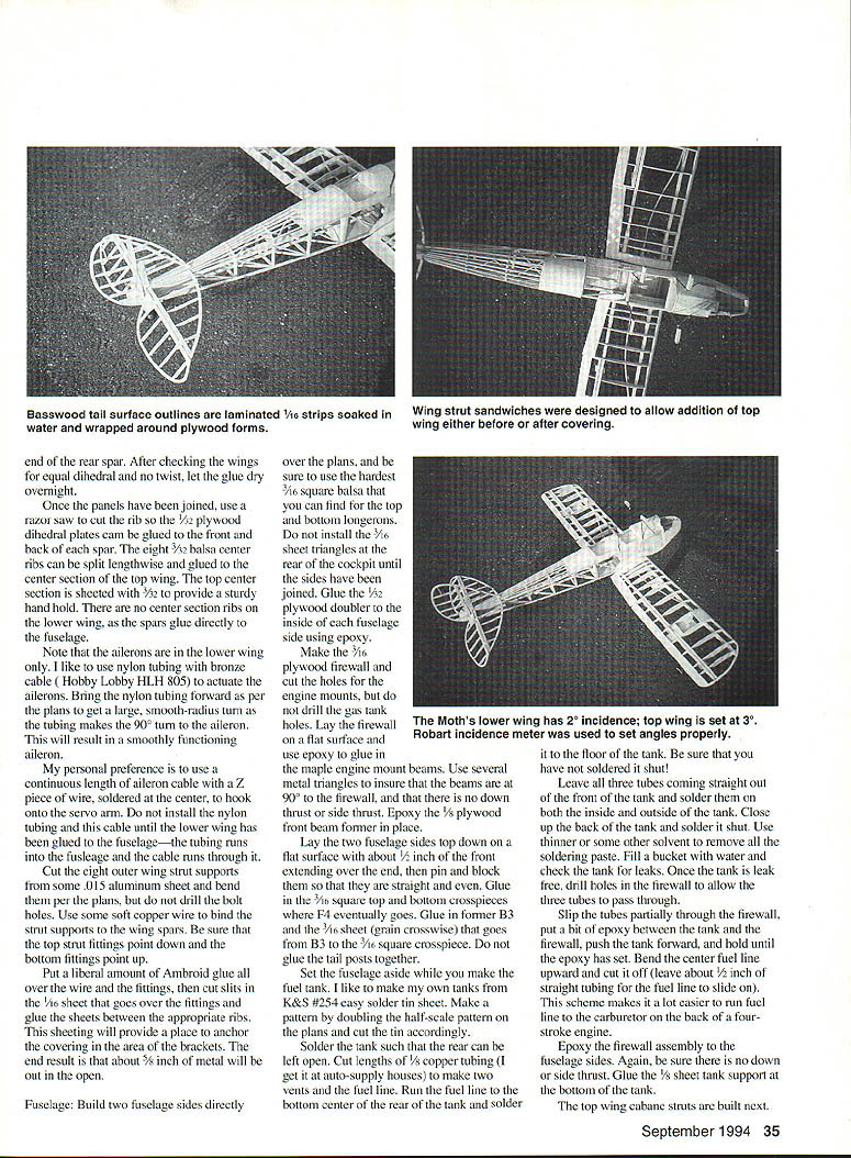
- Use an incidence meter to set the top wing to 3° incidence; adjust fuselage end of rear cabane strut and doublers to obtain proper incidence.
- Also measure wingtip to bench surface to confirm wing level before leaving glue to set.
- When gluing tail posts, do not force a sharp break in the longerons; glue tail posts together and allow longerons to take natural bend, widening formers F5–F7 if needed.
Servos and radio installation
- Make servo hatch cover from 1/16-inch plywood, curved to match lower longeron.
- Mount three servos side-by-side on a mount or on two 1/2-inch strips of 3/16 plywood.
- Slip 5/8-inch square maple servo mount rails into fuselage and seat servos in place.
- Mark screw holes on the 3/8 maple rails, remove servos, secure rails to rails and re-install; glue rails to fuselage side and former B3.
- Adjust rails so servo bottoms are about 1/8 inch above aileron servo plate and rails are parallel to top longerons.
- Aileron/throttle pushrods:
- Make two pushrods from hard 1/4-inch square balsa or 5/16-inch birch dowel; install threaded rod and Kwik-Links at control ends and form Z-bends where they exit the fuselage.
- Wrap threaded rod with thread and apply Ambroid for security.
- Install the 3/32-inch sheet in fuselage sides below stabilizer while pushrods are in place (pushrods are not removable without large exit holes).
- Throttle linkage:
- Install nylon tubing for throttle cable and solder threaded connectors to cable ends. Support tubing at a couple of points to ensure proper function.
Tail
- Standard construction for tail feathers.
- Note: 1/4 x 1/2 rear post in the vertical fin goes all the way to the bottom of the fuselage.
- For curved outline pieces, an option:
- Soak 1/16 square basswood in water, bend around 1/4-inch plywood forms, laminate four layers with white glue to create a 1/4-inch-wide outline 1/16-inch thick. Let dry, remove and plane smooth.
- Or cut outlines from 1/16-inch sheet balsa as a simpler method.
- Lower rudder hinge:
- Fabricate from .010 brass shim stock wrapped around 1/16 music wire and soldered together (not to the wire), then remove wire and file to shape — similar to Du-Bro or Klett hinges.
- Tailwheel:
- Bend 1/16 music wire to fit a 1/4-inch tail wheel; run through nylon Goldberg tailwheel bracket and brass hinge assembly; make a 90° rear bend per plans.
- Install stabilizer and fin:
- Cut a 1/4-inch vertical slot in tail post for stabilizer spar; glue stabilizer to top longerons 1/4 inch forward of fuselage end and check alignment.
- Cut 1/4-inch square slot in vertical fin post for rear stabilizer spar and glue vertical fin onto stabilizer and fuselage so the rear of vertical fin post is flush with fuselage end.
- Drill 3/32-inch hole through vertical fin post at stabilizer centerline and feed 3/32 music wire connector through for elevator halves.
- Install elevator hinges, glue connector wire into elevator holes, then install lower and upper rudder hinges and tailwheel assembly.
- Control linkages:
- Fit Kwik-Links at control surfaces and servo ends, adjusting lengths and Z-bends as needed.
Outer wing struts
- Make four outer wing struts from 1/8 x 3/4-inch basswood.
- Make eight aluminum plates (.015 sheet), drill 1/16-inch holes and cut slots in struts to accept plates.
- Epoxy plates into strut slots (avoid epoxy on exterior wood), stain struts with burnt umber and finish with clear dope.
- Fit struts into metal fittings on wings leaving ~3/64-inch clearance; drill 3/32-inch hole and install 2-56 bolts and nuts at both top and bottom fittings.
Covering and finish
- Covering materials:
- Fuselage and tail: lightweight silk or regular model silk.
- Wings: regular model silk worked well and stayed smooth.
- Technique:
- Brush silk on wet, allow to dry, then brush several coats of clear dope and spray silver dope over a brushed-on clear dope base.
- If covering while wing is on struts, iron-on coverings can be used; if covering separately, cut holes in sheeting as required to glue strut sandwiches to spars and then recover those holes.
- Notes on silk:
- Lightweight silk used for the fuselage and tail may loosen with time and hard use; some modelers accept this as a worn look reminiscent of service aircraft.
- Optional details:
- Engine cowl for display/photography (may be omitted for flying).
- Two-inch-scale pilot figure glued to look forward and slightly outboard for landing realism.
Flying
- Takeoff:
- Advance throttle slowly. Model will taxi until tail lifts; tap up elevator to initiate climb with little extra input.
- Once at a comfortable altitude, reduce throttle to about half.
- Handling:
- Requires coordinated rudder, elevator and aileron for clean turns; aileron-only turns look sloppy.
- The model flies realistically and predictably: slow, stately maneuvers, controllable at all altitudes.
- Aerobatics:
- Loop: dive slightly to build speed, pull back; Moth loops smoothly and slowly.
- Loop with a snap: full rudder and elevator just before top, release halfway through.
- Spin: gain altitude, pull up sharply, then as speed bleeds off give full rudder (either direction) and full up elevator; spins are balanced left or right.
- Slow roll: build speed, pull up, feed in aileron and some rudder to establish roll rate; finish with elevator control.
- Wingovers: low-altitude wingovers at sunset are especially striking with silver wings gleaming.
- Landing:
- Reduce throttle to near idle and fly a standard rectangular approach.
- At about 18 inches above ground, hold it level and the Moth will float; wheels may roll another 10 yards on grass after touch down.
- Pilot impressions:
- The Gipsy Moth is totally predictable, never doing anything untoward and remaining controllable even at low throttle settings.
- Flying it at the lowest reliable throttle setting adds to realism.
Engine notes
- Original model used an OS 20 four-stroke. O.S. later replaced the OS 20 with the OS 26 Surpass which fits the same mounts and bolt pattern.
- With the 26 Surpass the model may be slightly overpowered; adjust idle and throttle curve to obtain the lowest reliable idle to permit landing.
- Allow sufficient clearance around engine for access to mounting bolts and free throttle-arm movement.
Final notes
- The author reports hundreds of enjoyable flights and consistent praise for the model's realistic handling.
- Build light, check alignments and incidences carefully, and enjoy flying the Gipsy Moth with coordinated controls for the most authentic performance.
Transcribed from original scans by AI. Minor OCR errors may remain.

