
Glitch Buster
Part 1. Joe Utasi
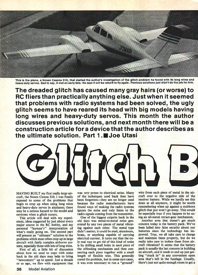
The dreaded glitch has caused more gray hairs (or worse) to RC fliers than practically anything else. Just when it seemed that problems with radio systems had been solved, the ugly glitch has reared its head again with big models having long wires and heavy-duty servos. This month the author discusses previous solutions; next month there will be a construction article for a device the author describes as the ultimate solution.
HAVING BUILT my first really large aircraft, the Nosen Cessna 310, I was finally exposed to some of the problems that begin to crop up when using long wires and heavy-duty servos in airplanes; there may be a serious hazard to the model and environs when a glitch occurs.
This article deals with my experiences, ideas suggested by just about every major source in the RC hobby, and my personal layman’s interpretation of what’s really going on. The second part will present an “ultimate” solution to the problems which most often crop up in large aircraft with fairly complex airborne systems, especially those with lots of long wires.
Background — old noise problems
First of all, a little discussion about how we used to cope with noise back in the old days may help bring newcomers up to speed. Just a decade or so ago we flew with equipment that was very prone to electrical noise. Many of the techniques used back then have been forgotten—they are no longer used because radio manufacturers have found ways to make radio systems ignore noise and only listen to the transmitter signals.
One of the biggest culprits back then was metal-to-metal noise generated by any two pieces of metal vibrating against each other. The metal type didn't matter; it could be steel, aluminum, brass, or anything capable of carrying electrical current. The only real way to get rid of this kind of noise is by drilling small holes in each piece of the offending mechanism and then connecting each piece together with a small length of flexible wire. This generally cured the problem, but in some rare cases it was even necessary to run a “ground” wire from each piece of metal in the aircraft over to the negative side of the receiver battery. While we hardly see this done at all anymore, it might be worth remembering when up against a stubborn glitch that just won't go away—especially with an all-metal retract-gear mechanism.
Battery packs and vibration
Another area that doesn't get much concern today is the battery pack. We've been lulled into false security about our batteries since the technology has improved. True, we all take care to charge and maintain them properly, but do we really take care to isolate them from aircraft vibration? The battery pack is usually the last concern in building an aircraft and tends to end up “stuck in” any convenient open area left in the fuselage. Usually, there's just not quite enough room to get a good fit or to adequately isolate it from vibration.
Present-day radio-control systems operate normal-size planes very well. Some simple modifications, such as a good layer of foam padding around either the receiver or the battery, will help isolate them from vibration. Cramming the battery into a tight spot with little or no padding may seem to work for a while, but after many flights the setup can suddenly start to go wild. The pilot begins doing the frantic “hand-dance” and wonders if the battery has finally given up.
Receiver antenna placement
Another area taken for granted is the receiver antenna. Some of us still remember the old days when we tried to position the antenna away from servo motors and battery wiring as it should be; others don't seem to care. “What the heck, it's got plenty of ground range,” they say. Wrong. What works on the ground doesn't always work in the air. Once it's up, it's too late to change your mind and move the antenna.
The best policy is to keep the antenna as far away as possible from anything electrical or metallic in the aircraft. Usually this means a straight run along the top of the fuselage back to the top of the fin. A small rubber band will maintain tension and keep the antenna nice and straight. Remember, antenna length is critical to proper tuning. The receiver antenna should be kept as straight as possible; running it along solid music-wire pushrods to the tail using wire cable systems is another caveat that should be heeded.
If wire lengths for controls are close to the same length as the antenna, strange things can happen to the radio system. During planning stages, long control cable runs should be broken randomly once per run with a wood or plastic insulating connector of some sort. The theory is that this will prevent any electrical “resonances” which might upset the radio system.
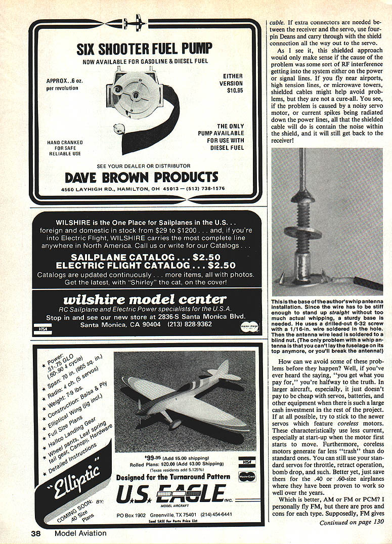
If the plane is already built and you've just discovered the glitch problem, the best alternative is to give a vertical whip antenna a try. This is simply a piece of music wire to which you solder your receiver antenna. Of course, you would remove a length of wire from the antenna equal to the length of the music wire.
I've been told that some of the newer receiver designs are especially touchy about antenna position and that the whip antenna is a sure way to get reliable operation. A while back, Kraft was offering a whip accessory for its radio system; it may still be available. It can't hurt, and it may save the plane.
Chokes and signal-line filtering
What about chokes? By now you've probably heard other fliers talking about chokes and how they helped or hurt their installations. In the old days we used to put chokes in the power leads to keep any RF picked up by the wiring from backing up into the receiver and causing havoc. With the size of the servos used in today's larger aircraft, and the high currents that must pass through the wiring, putting chokes in the power leads is generally out of the question.
I tried chokes in the power lead (using a choke capable of carrying the current), and it seemed to do more harm than good. With the chokes in the power lead, just waving the transmitter antenna near the aircraft would drive the system wild. I don't have a really good explanation, but it really happened.
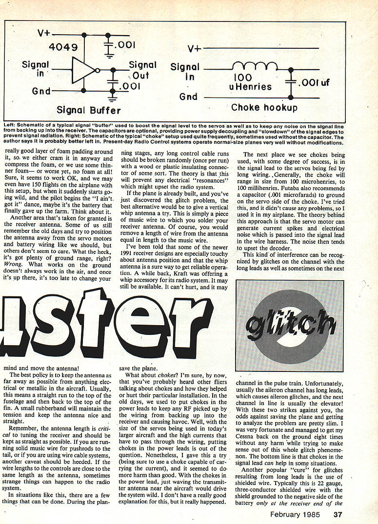
Chokes have been used with some success in the signal lead to servos fed by long wiring. Typically the choke will range in size from 100 microhenries to 100 millihenries. Futaba also recommends a capacitor (0.001 microfarads) to ground on the servo side of the choke. I tried this and it didn't cause any problems, so I used it in my airplane.
The theory is that the servo motor can generate current spikes and electrical noise which are passed into the signal lead in the wire harness. The noise then tends to upset the decoder. This kind of interference can be recognized by glitches on the channel with the long leads and sometimes on the next channel in the pulse train. Unfortunately, usually the aileron channel has long leads, which causes aileron glitches, and the next channel in line is usually the elevator. With those two strikes against you, the odds against saving the plane and analyzing the problem are pretty slim. I was fortunate and managed to get my Cessna back on the ground eight times without harm while trying to make sense of this whole glitch phenomenon. The bottom line is that chokes in the signal lead can help in some situations.
Shielded cable
Another popular cure for glitches from long leads is the use of shielded wire. Typically this is 22-gauge, three-conductor shielded wire with the shield grounded to the negative side of the battery only at the receiver end of the cable. If extra connectors are needed between the receiver and the servo, use four-pin Deans and carry the shield connection all the way through to the servo.
This shielded approach makes sense only if the problem is some sort of RF interference getting into the system on the power or signal lines. If you fly near airports, high-tension lines, or microwave towers, shielded cables might help, but they are not a cure-all. If the problem is caused by a noisy servo motor, or current spikes being radiated down the power lines, the shielded cable will simply contain the noise within the shield and it will still get back to the receiver.
Equipment choices: servos and radio types
How can we avoid some of these problems before they happen? Well, if you've ever heard the saying “you get what you pay for,” you're halfway to the truth. In larger aircraft it doesn't pay to be cheap with servos, batteries, and other equipment when there is such a large cash investment in the rest of the project. If possible, stick to the newer servos that feature coreless motors. These use less current—especially at startup—and generate far less electrical “trash” than standard motors.
You can still use standard servos for throttle, retract operation, bomb drop, and similar functions. Better yet, save them for the .40 or .60-size airplanes where they have been proven to work well.
Which is better—AM, FM, or PCM? I personally fly FM, but there are pros and cons for each type. Supposedly FM gives better noise immunity, especially for metal-to-metal noise; that is why so many helicopter pilots use FM. AM is fine, too. What you don't see discussed is that the AM receiver design has less noise in the front-end circuitry. New narrow-band designs are first-rate and offer good selectivity, sensitivity, and overall performance. Trouble is, if someone on your frequency turns on, it's all over. With FM, if you're lucky you might get by if someone turns on with their antenna down and your signal still keeps the receiver “captured.” I seem never to be lucky; maybe your luck is better.
For those who can afford it, there is PCM. Contrary to popular belief, if someone on your frequency turns on you will still likely crash. The difference is in how you crash. If the interference is weak or intermittent, PCM may be able to read “between the lines” and maintain control, although response may seem slow. If the interference is serious and constant, the receiver may go into a fail-safe mode where the servos move to a predetermined position. That may be fine for a docile old-timer, but if you're flying a 30-lb ship with 5 hp and neutral stability, head for cover. If I could afford it, I'd fly PCM.
Other glitch-reduction devices
How about the many different “glitch stop” gadgets that are available? Basically, these devices consist of signal buffers made from logic devices (buffers or inverters) which boost the signal strength to the servo and prevent noise on the signal line from getting back into the decoder. In most cases these devices do the trick, unless you have a more serious problem.
Another good item is a system that allows the use of separate battery packs for powering the receiver and servos. RAM has such a product on the market. It goes a long way toward cleaning up many problems created by long leads and noisy servos. In many cases, switching to separate battery packs for the receiver and servos will completely eradicate glitch problems. It's a little extra wiring and requires patience, but the results are well worth it.
New theory about long leads and imbalance
Finally, here is something really new. After about two days on the phone with an RF expert who has designed some popular radio sets, I uncovered a new theory about long leads and glitches. It seems that today's receiver designs all use what is referred to as a “single-ended” front end. Put simply, we just have one wire coming from the receiver that we call the antenna. Think about this: just about every other kind of antenna that exists is a dipole, or double-sided antenna.
Look at your TV antenna or the rabbit ears on the set. Even CB antennas are balanced for maximum performance. Those that aren't dipoles usually use a ground plane that electrically creates a mirror image of the top part of the antenna and ends up being balanced.
In our RC systems we don't have a nice metal hood to act as a ground plane. All we have is the circuitry of the receiver and the small amount of wiring we've become used to in small installations. When we begin to add substantial amounts of wiring to the airborne system, this critical balance in the airborne system is upset, inviting all sorts of unexplainable glitches. Even using separate battery packs for the receiver and servos won't cure this imbalance, because we have a common ground connection between the battery packs and all that wiring is still tied together.
How, then, can we get away from this problem?
The solution is readily obvious after a month of tearing your hair out: completely isolate the flight control system from the receiver. This is accomplished by using optical couplers that use infrared light to transfer the signal from the receiver to the airborne system. In addition, use a separate battery pack to power the airborne system. After the optical isolation, follow up with a signal buffer as described earlier. Thus you have no connection between the receiver and the servos, wiring, or servo battery pack: total isolation plus signal buffering.
Tune in next month for a full construction article on a real glitch buster.
Practical measures (summary)
- Keep receiver antenna straight and well away from electrical/metallic items.
- Isolate receiver and battery from vibration with foam padding.
- Break long control cable runs with insulating connectors to prevent resonances.
- Consider chokes in servo signal leads (and small capacitors to ground) where appropriate.
- Use shielded cable only when external RF is suspected; shields are not a cure for noisy servos.
- Use coreless servos and quality batteries to reduce electrical noise.
- Consider signal buffers, separate servo/receiver power packs, and optical isolation for worst-case installations.
Transcribed from original scans by AI. Minor OCR errors may remain.

