
Glitch Buster
LAST MONTH we discussed many techniques used in the past (and present) to try to rid our aircraft of the phenomenon known as "glitches." By now, most of us have heard horror stories about glitches caused by long servo leads, especially on the ailerons, but no real tangible explanation had come along—until now. The best way to attack the problem is to implement the correct "cure" before you even fly the airplane. This is especially true if cable runs to the servos exceed 48 inches. There's no point in taking chances to see "if it will work" when there is a simple and effective alternative: the Glitch Buster.
With the Glitch Buster installed in the aircraft, several factors work to your advantage:
- You can use the small battery pack and switch harness that came with your radio to power the receiver by itself. The receiver then gets nice, clean, trash-free DC voltage and will operate reliably for several hours on a single charge, assuring the radio link to the ground for the entire flight.
- There is optical coupling between the receiver's decoder outputs and the servos, which isolates the receiver from noise and interference on the servo wiring.
- Using a separate airborne battery for servo power prevents servo motor current spikes and motor noise from getting back to the receiver.
How it works
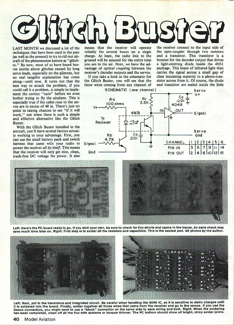
The three wires from any receiver channel connect to the input side of an opto-coupler through two resistors and a transistor. That transistor boosts the decoder output and drives a light-emitting diode inside the 4N31 opto-coupler package. The infrared light crosses a small insulating gap to a photo-transistor sealed inside the six-pin package, which converts the light back into an electrical waveform (at Pin 5 of the 4N31).
Because neither signal nor power leads are electrically connected between receiver and servos, receiver noise, current spikes, and RF interference riding on exposed servo wiring cannot penetrate and upset receiver circuitry.
The opto-coupler inverts the waveform, so the outputs are routed to a 4049 inverter/buffer. The 4049 does two things:
- It reinverts the signal to the correct polarity.
- It boosts the signal level, allowing the servo battery pack voltage to be used as headroom.
Most receivers put out servo pulses between 3 and 4 volts because of internal voltage regulators. The extra volt provided by the servo battery represents roughly a 20% increase in signal amplitude reaching the servo, which is especially important in areas prone to RF interference (paging systems, power lines, etc.).
Lastly, because the servos use a separate battery, motor current spikes and noise stop short of getting back to the receiver. The bottom line: you've taken a practical step to prevent potential glitches.
Real-world results
The system shown helped a Futaba J-series FM system tremendously when no other combination of gadgets would work. Some systems tolerate noise and long leads better than others, but it's not worth taking a chance when you can do something about it. The Glitch Buster will help you cope with problems created by long servo wiring. Also remember that a backup battery pack can help avoid a crash; a single pack for the receiver is adequate if well cared for, though I recommend a backup pack on the servo side if feasible.
Construction and assembly
Assembly is simple and goes fast if you've built a few electronics kits.
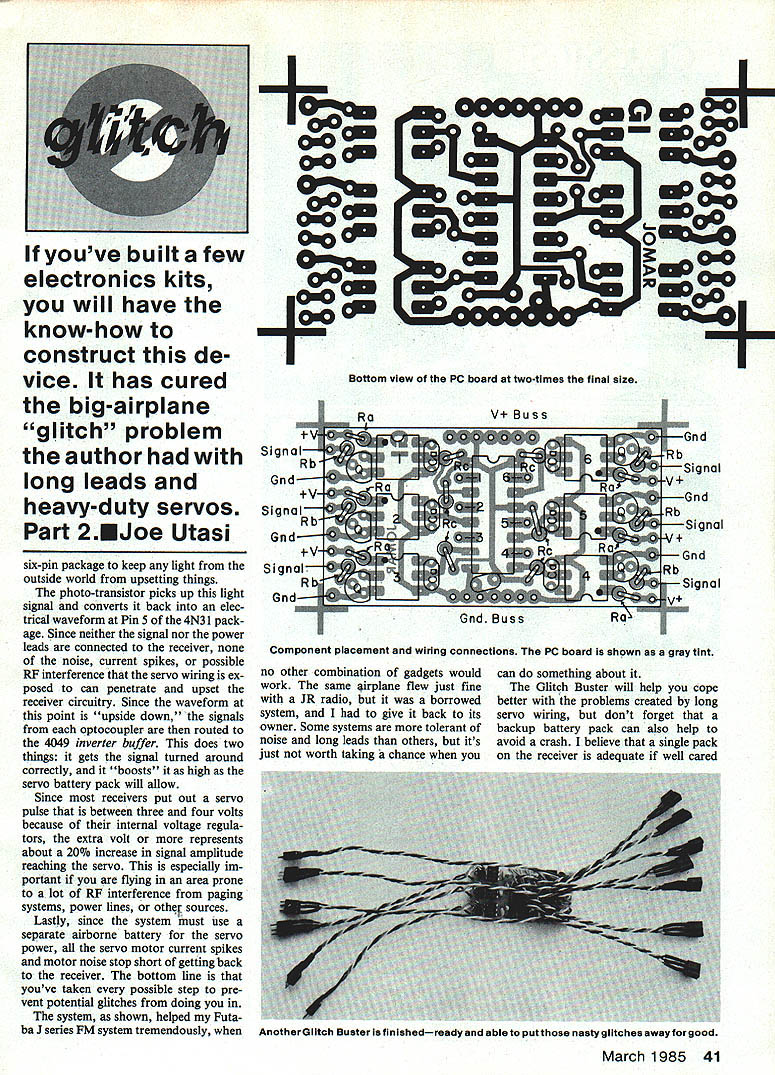
- Solder in all resistors and capacitors.
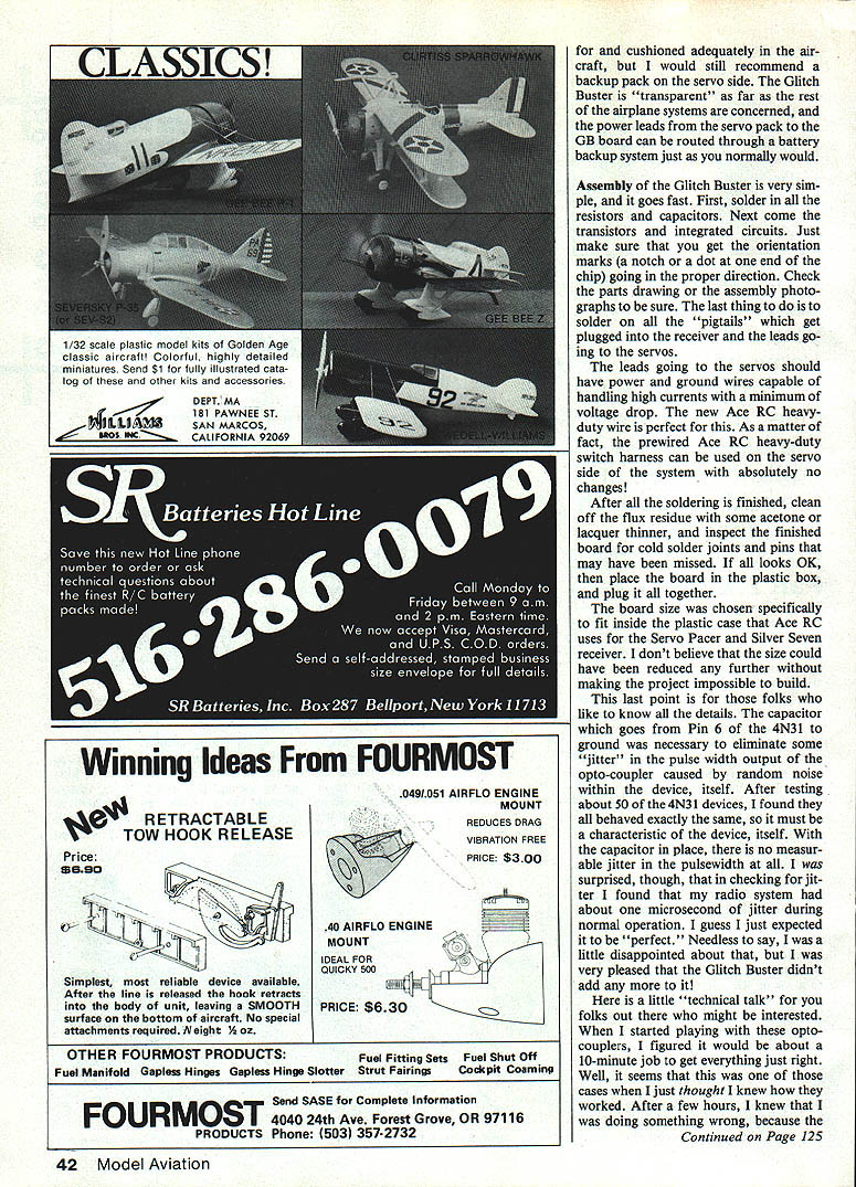
- Solder the transistors and integrated circuits. Make sure orientation marks (notch or dot) are correct; check the parts drawing or assembly photos.
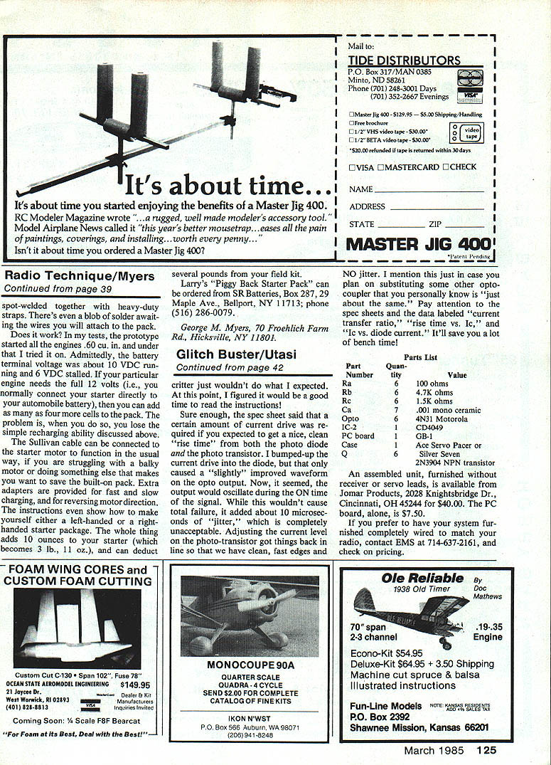
- Solder on all the "pigtails" that plug into the receiver and the leads going to the servos.
- Use power and ground wires capable of handling high currents with minimum voltage drop for the servo leads. The new Ace RC heavy-duty wire is ideal.
- The prewired Ace RC heavy-duty switch harness can be used on the servo side with no changes.
- After soldering, clean flux residue with acetone or lacquer thinner and inspect the board for cold solder joints or missed pins.
- Place the board in the plastic case and plug everything together.
The board size was chosen to fit inside the plastic case Ace RC uses for the Servo Pacer and Silver Seven receiver. Reducing the size further would make the project difficult to build.
Technical notes
- A capacitor from Pin 6 of the 4N31 to ground was necessary to eliminate jitter in the pulse-width output of the opto-coupler caused by random noise inside the device. After testing about 50 4N31 devices, they all behaved the same; with the capacitor in place, there is no measurable jitter in the pulse width.
- During testing I found about one microsecond of jitter in my radio system during normal operation. The Glitch Buster did not add to that jitter.
- When substituting opto-couplers, pay attention to the data sheet parameters: "current transfer ratio," "rise time vs. Ic," and "Ic vs. diode current." Proper current drive into the diode and transistor is required for clean rise times and to avoid oscillation (which can add microseconds of jitter).
Parts list
- Ra: 6 — 100 ohms
- Rb: 6 — 4.7K ohms
- Rc: 6 — 1.5K ohms
- Ca: 6 — 0.001 µF mono ceramic
- IC-2: 6 — 4N31 opto-coupler
- PC board: 1 — (as shown)
- Case: 1 — Ace Servo Pacer or similar
- Q: 6 — 2N3904 NPN transistor
Availability and pricing
- An assembled unit, furnished without receiver or servo leads, is available from Jomar Products, 2028 Knightsbridge Dr., Cincinnati, OH 45244 for $40.00.
- The PC board alone is $7.50.
- If you prefer a system furnished completely wired to match your radio, contact EMS at 714-637-2161 for pricing.
Part 2 — Joe Utasi
Transcribed from original scans by AI. Minor OCR errors may remain.

