
Glow Plug Heater
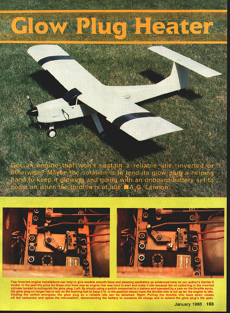
Got an engine that won't sustain a reliable idle, inverted or otherwise? Maybe the solution is to lend its glow plug a helping hand to keep it glowing and going with an onboard battery set to come on when the throttle is at idle. — A. G. Lennon
Background
Inverted engine installations, whether two-stroke or four-stroke, have many advantages. The high thrust lines provide more propeller clearance, aid stability, and lend themselves to well-streamlined, low-drag cowlings. But they do have one drawback: while idling or at low rpm in flight such installations are prone to the engine dying. In fact, four-stroke engines will often quit at low rpm even when installed upright, due to glow plug cooling caused by the reduced frequency of the power stroke.
Solution: Onboard Glow Plug Heating System
The solution devised here is an inexpensive onboard glow plug heating system which energizes the glow plug at low rpm only and permits the use of an external power source for engine starting—either a 1-1/2 volt battery or a power panel. A separate on-off switch for the glow driver is not required: when both throttle stick and trim lever are at their lowest positions, the throttle closes, the engine stops, and current to the glow plug is cut off.
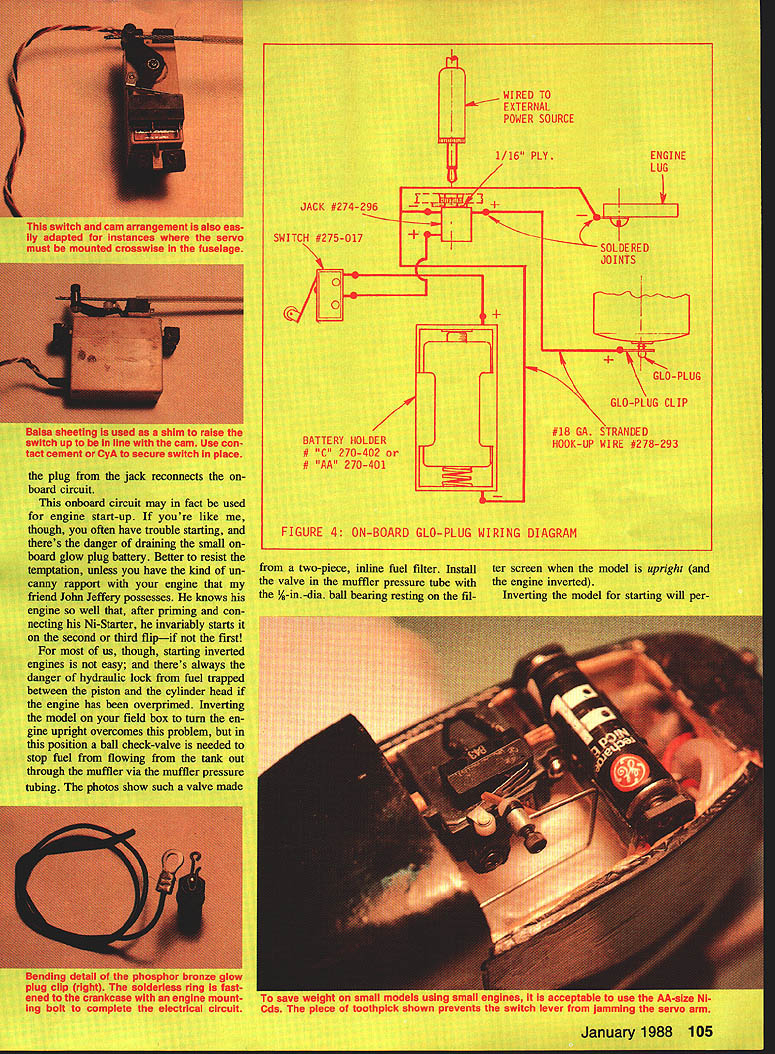
An important safety feature is the location of the jack: it should be situated well away from the rotating propeller so the plug can be safely removed to disconnect the external power source after the engine starts. This is much safer than removing a glow plug clip, particularly on some four-stroke engines where the plug is at the front of the cylinder head. When the plug is inserted in the jack, the onboard circuit is interrupted and the throttle and trim levers may be moved for engine start-up with no drain on the onboard glow battery. Removal of the plug from the jack reconnects the onboard circuit.
Installation
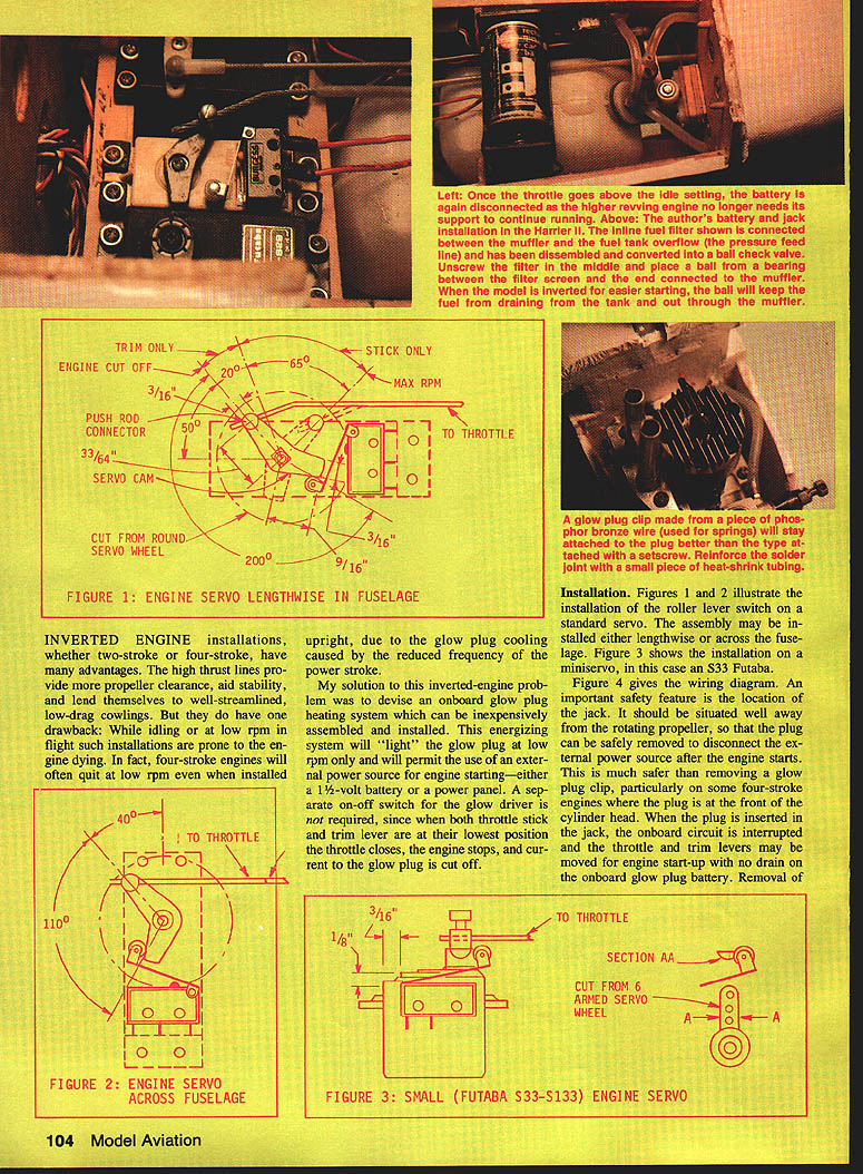
- Figures 1 and 2 illustrate installation of the roller lever switch on a standard servo. The assembly may be installed either lengthwise or across the fuselage.
- Figure 3 shows the installation on a miniservo (S33 Futaba). Figure 4 gives the wiring diagram.
- The roller lever switch is mounted on sheet balsa to raise it so that the roller is centered on the servo arm.
- The servo arm cams used in figures 1 and 2 are cut from large circular servo wheels. The Futaba wheel is 13/16 in. in diameter; the splined connection to the servo output shaft permits the arm to be positioned correctly. If your engine servo has a square-type output shaft, the servo arm must be cut and located correctly relative to the square, as shown in figure 1. Figure 3 illustrates the arm for a miniservo.
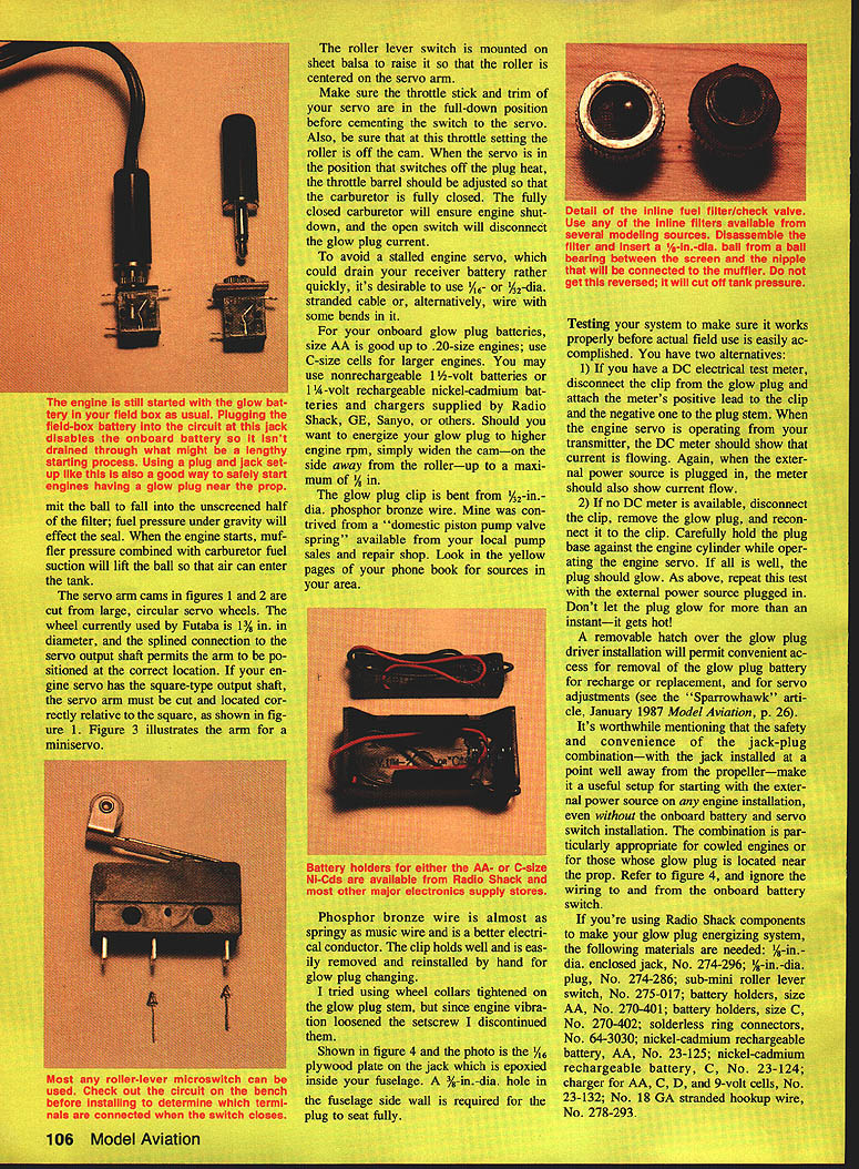
- Make sure the throttle stick and trim of your transmitter are in the full-down position before cementing the switch to the servo. Also be sure that at this throttle setting the roller is off the cam. When the servo is in the position that switches off the plug heat, the throttle barrel should be adjusted so that the carburetor is fully closed. A fully closed carburetor ensures engine shutdown, and the open switch will disconnect the glow plug current.
- To avoid a stalled engine servo, which could drain your receiver battery rather quickly, use 1/16- or 1/32-in. stranded cable or, alternatively, wire with some bends in it.
- If you want the glow plug energized at higher engine rpm, simply widen the cam (on the side away from the roller) up to a maximum of 1/2 in.
Figure labels:
- Figure 1: Engine servo lengthwise in fuselage.
- Figure 2: Engine servo across fuselage.
- Figure 3: Small (Futaba S33-S133) engine servo.
- Figure 4: Wiring diagram and jack/plate detail.
Shown in figure 4 (and in the photo) is a 1/16-in. plywood plate on the jack which is epoxied inside the fuselage. A 3/16-in.-dia. hole in the fuselage sidewall is required for the plug to seat fully.
Starting and the External Power Option
This onboard circuit may be used for engine start-up, but using an external power source for starting is recommended to avoid draining the small onboard glow plug battery. The jack-and-plug arrangement makes external starting safer because the jack can be mounted well away from the propeller. The combination is particularly appropriate for cowled engines and for engines whose glow plug is located near the prop.
Inverted-Start Fuel Precautions
For inverted engines, starting can be difficult and there's always a danger of hydraulic lock from fuel trapped between the piston and the cylinder head if the engine has been overprimed. Inverting the model on your field box to turn the engine upright overcomes this problem, but in this position a ball check valve is needed to stop fuel from flowing from the tank out through the muffler via the muffler pressure tubing.
- One recommended valve is made from a two-piece inline fuel filter. Install the valve in the muffler pressure tube with the 1/8-in. dia. ball bearing resting on the filter screen when the model is upright (and the engine inverted).
- Inverting the model for starting will permit the ball to fall into the unscreened half of the filter; fuel pressure under gravity will effect the seal.
- When the engine starts, muffler pressure combined with carburetor fuel suction will lift the ball so that air can enter the tank.
Clip and Wire Notes
Phosphor bronze wire is almost as springy as music wire and is a better electrical conductor. The clip holds well and is easily removed and reinstalled by hand for glow plug changing.
Testing
Test the system before actual field use. Two alternatives:
- If you have a DC electrical test meter:
- Disconnect the clip from the glow plug and attach the meter's positive lead to the clip and the negative lead to the plug stem.
- When the engine servo is operating from the transmitter, the DC meter should show current flow.
- When the external power source is plugged in, the meter should also show current flow.
- If no DC meter is available:
- Disconnect the clip, remove the glow plug, and reconnect it to the clip.
- Carefully hold the plug base against the engine cylinder while operating the starter. If all is well, the plug should glow.
- Repeat this test with the external power source plugged in.
- Do not let the plug glow for more than an instant—it gets hot.
A removable hatch over the glow plug driver installation permits convenient access for removal of the glow plug battery for recharge or replacement, and for servo adjustments.
Materials (Radio Shack components example)
If using Radio Shack components, the following materials are suggested:
- 1/4-in.-dia. enclosed jack, No. 274-296
- 1/4-in.-dia. plug, No. 274-286
- Sub-mini roller lever switch, No. 275-017
- Battery holder, size AA, No. 270-401
- Battery holder, size C, No. 270-402
- Solderless ring connectors, No. 64-3030
- Nickel-cadmium rechargeable battery, AA, No. 23-125
- Nickel-cadmium rechargeable battery, C, No. 23-124
- Charger for AA, C, and 9-volt cells, No. 23-132
- No. 18 GA stranded hookup wire, No. 278-293
Battery sizing: use AA for engines up to .20 size; use C-size cells for larger engines. You may use nonrechargeable 1-1/2-volt batteries or 1-1/4-volt rechargeable nickel-cadmium batteries and chargers from Radio Shack, GE, Sanyo, or others.
Final Notes
The safety and convenience of the jack-plug combination—with the jack installed well away from the propeller—make it useful for starting with an external power source on any engine installation, even without the onboard battery and servo switch. Refer to figure 4 for wiring details and ignore the wiring to and from the onboard battery switch if you choose not to install the onboard battery.
Transcribed from original scans by AI. Minor OCR errors may remain.

