
GOBLIN: MINIMUM INVESTMENT FOR MAXIMUM FUN
BILL WINTER & JOHN HUNTON
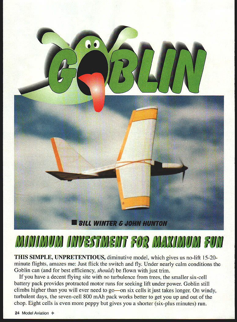
This simple, unpretentious, diminutive model, which gives no-lift 15–20-minute flights, amazes me: just flick the switch and fly. Under nearly calm conditions the Goblin can (and for best efficiency should) be flown with just trim.
If you have a decent flying site with no turbulence from trees, the smaller six-cell battery pack provides protracted motor runs for seeking lift under power. Goblin still climbs higher than you will ever need to go—on six cells it just takes longer. On windy, turbulent days the seven-cell 800 mAh pack works better to get you up and out of the chop. Eight cells is even more peppy but gives you a shorter (six-plus minutes) run.
The short-coupled Goblin will seek and turn into lift. On a weak-lift day, if you are turning left and the model changes off to turning right, it is trying to tell you something: leave it alone.
I am convinced that if Bill Winter looks at a model it will go up, and if he looks away it will sink. I am not that gifted, so on a strong-lift day, look for the model to "wiggle" when it enters lift, then heel it over to stay in the lift.
Performance notes
- The Speed 400 with the prescribed gearbox, prop, and batteries is surprisingly effective.
- Motor performance in flight was better than calculated; verification at a steady low altitude (about 100 ft) showed the numbers checked out.
- During a typical flight, early high power requires almost full down trim; as battery power diminishes, progressively reduce down trim until neutral for landing.
- Caution: Goblin is aerodynamically sleek. You could possibly exceed the airplane's structural capability in a dive out of a thermal. The preferred rapid-descent method is to rock it into a wings-vertical spiral; if you must dive, recover with very gentle, smooth up-elevator input.
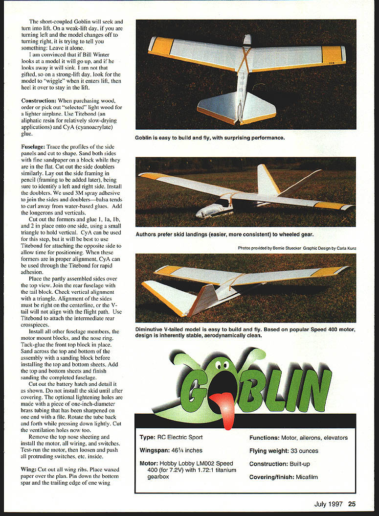
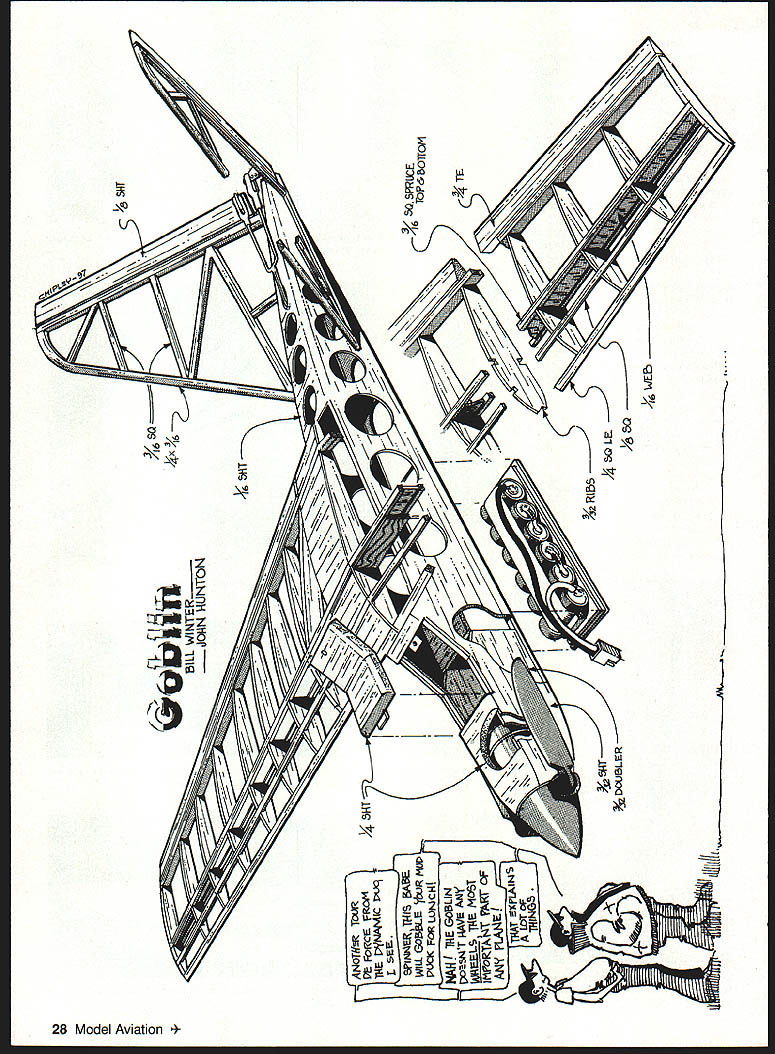
Construction
When purchasing wood, order or pick out "selected" light wood—the lighter the airplane the better. Use Titebond (an aliphatic resin; relatively slow-drying) for general assembly and CA (cyanoacrylate) glue for spot and rapid-adhesion applications.
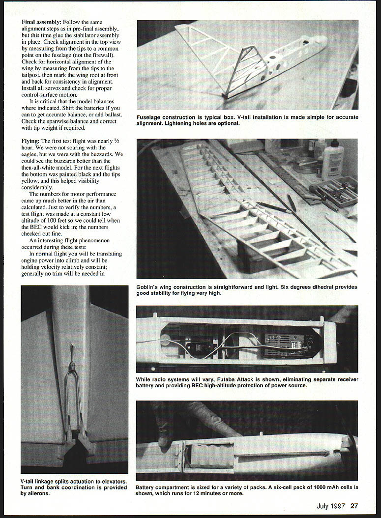
Fuselage
- Trace the profiles for the side panels and cut to shape. Sand both faces with fine sandpaper on a block while panels remain flat.
- Cut side doublers similarly. Lay out the side framing in pencil (framing is added later); be sure to identify left and right sides.
- Install the doublers. We used 3M spray adhesive to join sides and doublers—balsa tends to curl away from water-based glues. Add longerons and verticals.
- Cut out the formers. Glue formers 1, 1a, 1b, and 2 in place onto one side using a small triangle to hold vertical. CA can be used at this step, but use Titebond when attaching the opposite side to allow time for positioning. When alignment is correct, CA can be applied through the Titebond joint for rapid adhesion.
- Place the partly assembled sides over the top view. Join the rear fuselage to the tail block. Check vertical alignment with a triangle—alignment of the sides must be right on the centerline or the V-tail will not align with the flight path.
- Use Titebond to attach intermediate rear crosspieces. Install remaining fuselage members, motor-mount blocks, and the nose ring. Tack-glue the front top block in place.
- Sand across the top and bottom of the assembly with a sanding block before installing top and bottom sheeting. Add the top and bottom sheets and finish-sand the completed fuselage.
- Cut out and detail the battery hatch as shown in the plans. Do not install the skid until after covering.
- Optional lightening holes: use a piece of 1" diameter brass tubing sharpened on one end and rotate it back and forth while pressing down lightly. Cut ventilation holes now as well.
- Remove the top nose sheeting to install the motor, wiring, and switches. Test-run the motor, then loosen and push all protruding switch actuators and similar items inside so nothing binds.
Wing
- Cut out all wing ribs. Place waxed paper over the plan and pin down the bottom spar and the trailing edge of one wing panel.
- Insert bottom center-section sheeting and ribs, tilting root and tip ribs as shown on the plan. Glue ribs in place.
- Add the leading edge, top spar, web members, and turbulator spar. Install the spar joiner and the plywood joiner.
- Lightly crack the plywood joiner for the 5° forward sweep (do not break it); glue the joiner and top sheeting to the wing panel.
- Build the other wing similarly, but do not sheet the top center section until the wing halves have been joined. When basic wings are assembled, add remaining top sheeting and fixed trailing-edge parts at the root.
- Cut ailerons to shape (use 3/16" x 3/4" TE stock if available) and install aileron linkage.
- Cut a hole in the bottom center section for the servo installation. After covering, install hardwood servo-mount rails onto the balsa sheeting and mount the servo and linkage.
- Use a gunsmith’s trick to accurately mate wing to fuselage:
- Lay strips of masking tape on the bottom of the wing where it mates to the fuselage; apply lipstick to the tape.
- Mount the wing, then remove it. Sand away fuselage material where the lipstick shows.
- Repeat until you get a good, tight match.
- Finish-sand the wing panels with fine paper on a large block. Do not oversand or you will lose the airfoil profile.
Empennage
- Build up the stabilators over the plans. Sand smooth with fine paper on a block.
- Round off the leading edges and complete the empennage assembly as shown in the plans.
- Insert bottom center-section sheeting and all ribs (tilt root and tip ribs as shown) and glue in place.
- When the stabilators are built and sanded, proceed to pre-final assembly.
Pre-final assembly
- Join the stabilators at 90° and slip them into the fuselage slot.
- Lay the fuselage on a bench. Check and trim the fuselage if necessary so that the stabilator center section sits at 45° with respect to the work surface (check both sides). The stabilator center section must lie along the centerline of the bottom of the fuselage for proper decalage. Do not glue in place at this time.
- Fit the wing to the fuselage and check for level relative to the bench. Drill holes for the wing hold-down dowels but do not install them until covering and finishing are complete.
Covering
- Prepare all surfaces by sanding with a block; touch up curves with a sanding pad.
- Apply two coats of Balsarite, sanding lightly with #150 production paper after each coat.
- Micafilm is a very strong and light covering. Follow the manufacturer’s printed instructions closely.
- Cover the wing bottom first, then fasten to the workbench with the trailing edge blocked up 3/8". Cover the top. The object is to get 3/8" twist (washout) into each wing panel—this is important for stall characteristics and gliding efficiency.
Final assembly
- Repeat the alignment checks used in pre-final assembly, and this time glue the stabilator assembly in place.
- Check top-view alignment by measuring from the tips to a common point on the fuselage (not the firewall). Check wing horizontal alignment by measuring from the tips to the tailpost; mark the wing root at front and back for consistent alignment.
- Install all servos and verify proper control-surface motion.
- It is critical that the model balances where indicated. Shift batteries to obtain accurate balance, or add ballast. Check spanwise balance and correct with tip weight if required.
Flying
- The first test flight was nearly half an hour. Visibility improvements: paint the bottom black and the tips yellow.
- Expect motor-run duration and trim changes as battery voltage decays: early in the flight you will be fast and need down trim; as power drops, reduce down trim until neutral for landing.
- For rapid descent, rock the model into a wings-vertical spiral. If a dive is required, recover gently to avoid structural overload.
- Efficiency results from a fortunate combination of area, loading, foil, sweep, V-tail, and possibly the covering material (unfinished white Micafilm, with a little "grain," may add to efficiency by affecting turbulence).
We would like to hear from you about your results.
Bill Winter 12811 Melville Ln. Fairfax, VA 22033
John Hunton 9154 Rixeyville Rd. Rixeyville, VA 22737
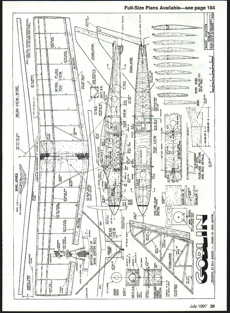
Plans and drawings (as shown)
- Wing plan — top view
- Rear view — wing
- Stabilator — side view, top view
- Bottom view of wing center section
- Wing joiner
- Ribs / wing ribs
Designed by Bill Winter — Drawn by John Hunton
Transcribed from original scans by AI. Minor OCR errors may remain.

