
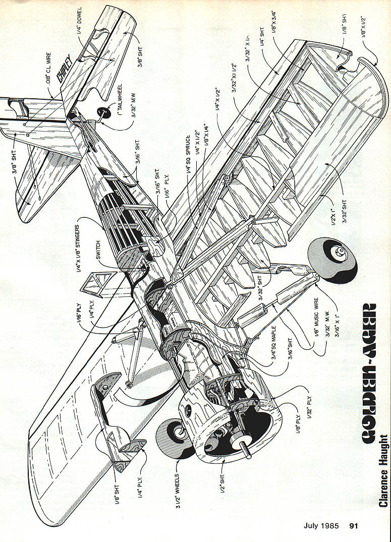
Golden-Ager
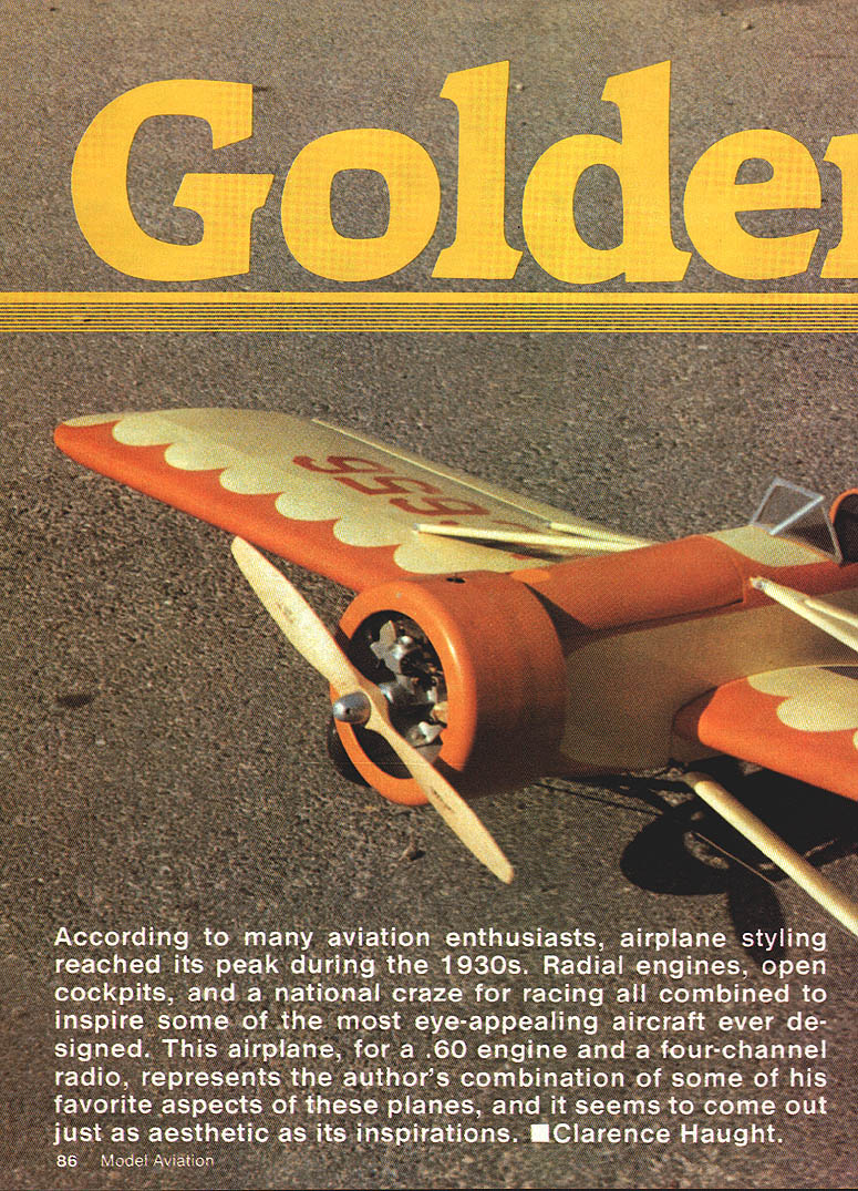
According to many aviation enthusiasts, airplane styling reached its peak during the 1930s. Radial engines, open cockpits, and a national craze for racing combined to inspire some of the most eye‑appealing aircraft ever designed. This airplane, for a .60 engine and a four‑channel radio, represents the author's combination of some of his favorite aspects of these planes, and it seems to come out just as aesthetic as its inspirations.
By Clarence Haught.
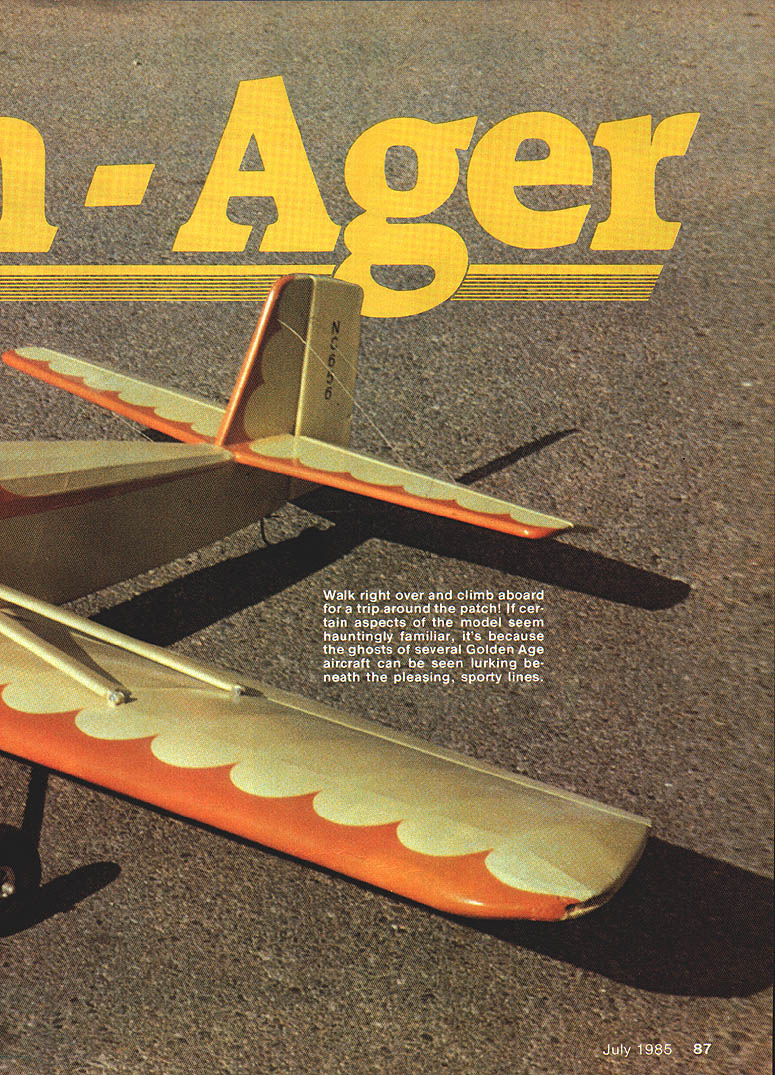
Walk right over and climb aboard for a trip around the patch! If certain aspects of the model seem hauntingly familiar, it's because the ghosts of several Golden Age aircraft can be seen lurking beneath the pleasing, sporty lines.
One can find a great deal of interest and support for all of the general classifications of aircraft: WW I, racing, sport, commercial, and on and on. It's incredible when you think about the vast number of designs that have actually reached the flight stage, let alone the quantity produced of all the successful ones. This makes it easy, or difficult, as the case may be, to find a favorite "look" or category of aviation.
One of my favorite eras is the so‑called Golden Age era of the 1930s. I like this era because of the classic look of the designs of this period. Being partial to "round engines" cinches it for me.
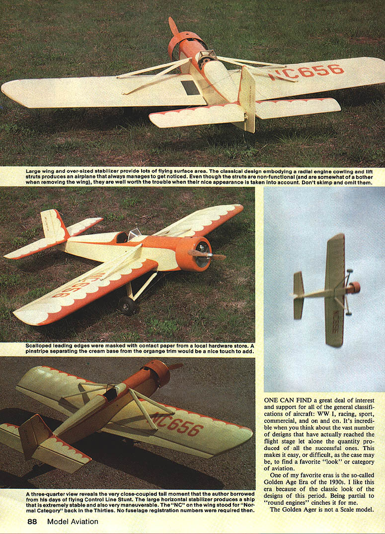
The Golden Ager is not a scale model. It is a composite of features of several airplanes of the Thirties, including a radial‑engine cowling. Wing struts, faired landing gear, and tail brace wires add to the nostalgic appearance. Certain design features were borrowed from many years of control‑line stunt experience. The short tail moment, made possible by the large stabilizer, full‑span tapered ailerons, and a long nose moment were all part of an experiment that proved effective for an RC sport model.
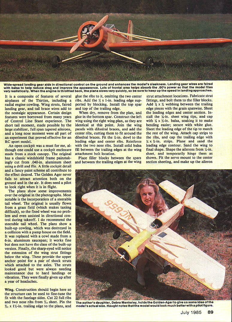
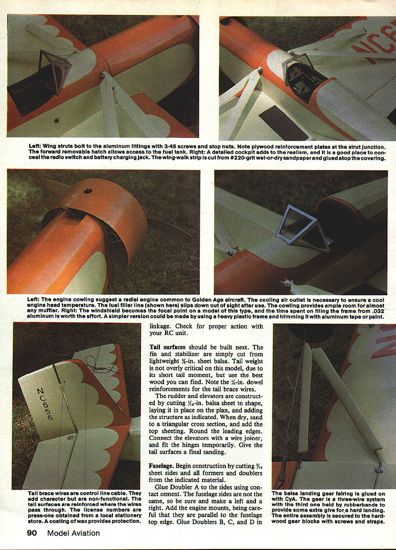
An open cockpit was a must for me, although one could use a cockpit enclosure made from a stock canopy. The original has a classic windshield frame painstakingly cut from 0.040‑in. aluminum sheet using a drill and file. A little cockpit detail and a fancy paint scheme all contribute to the desired effect. The Golden Ager never fails to attract attention both on the ground and in the air. It does need a pilot to look right when it is in flight.
The plans show some improvements over the original in the photographs. Most notable is the incorporation of a steerable tail wheel. The original is usually flown from a grass field (which makes taxiing difficult), so the fixed tail wheel was no problem and even assisted in directional control during takeoff. I do recommend the steerable tail wheel. The plans show a built‑up cowling, which was destroyed in a collision with a pump house on the field. It was replaced with a cowl made from a 6‑in. aluminum saucepan; it works fine but does not have the class of the built‑up version. Finally, the sharp‑eyed will notice the extension of the wing strut fittings below the wing. These provide the upper anchor point for a pair of shock struts which attached to the axles. The struts looked good but were always needing maintenance due to hard landings or vibration. They were finally given up after a year of headaches.
Wing Construction
Construction should begin with the wing so the structure can be used to fine‑tune the fit with the fuselage sides.
- Cut 22 full ribs and two nose ribs from 3/32‑in. sheet.
- Pin the 3/32 x 1/4‑in. trailing edge to the plans and glue the ribs to it, omitting the two center ribs.
- Add the 1/2 x 1‑in. leading edge supported by blocking. Install the top spar and top of the trailing edge.
When dry, remove the wing from the plan and glue in the bottom spar. Construct the left wing using the right‑wing plan, as they are identical at this point. Join the wing panels with dihedral braces, then add the center ribs, cutting them to fit around the dihedral braces. Fit the 1/4‑in. dowel in the leading edge and center ribs and reinforce with the two nose ribs. Install solid balsa fill between the trailing edges at the wing‑attachment bolt location.
Place filler blocks between the spars and between the trailing edges at the wing‑strut attachment locations. Fabricate strut fittings and bolt the filler blocks in place. Add 1/4 x 1/8‑in. webbing between the trailing edge pieces with the grain spanwise. Sheet the leading edges and center section. Install the 1/8‑in. sheet wing tips, and cap with 1/8 x 1/4‑in. balsa, soaking it to make bending easier; secure with white glue. Sheet the leading‑edge tip to match the rest of the wing.
Attach cap strips to ribs and cap the trailing edge with 3/32‑in. strips. Plane and sand the leading‑edge contour and sand the wing to final shape. Shape the ailerons from 1/8‑in. sheet, and temporarily hinge them as shown on the plans. Fit the servo mount to the center‑section sheeting and make up the aileron control linkage. Check for proper action with your RC unit.
Tail Surfaces
Tail surfaces should be built next.
- Cut the fin and stabilizer from lightweight 3/16‑in. sheet balsa. Tail weight is not overly critical on this model due to its short tail moment, but use the best wood you can find.
- Note the 1/4‑in. dowel reinforcements for the tail brace wires.
Construct the rudder and elevators by cutting 1/16‑in. balsa sheet to shape, laying it in place on the plan, and adding the structure as indicated. When dry, sand to a triangular cross section and add the top sheeting. Round the leading edges. Connect the elevators with a wire joiner and fit the hinges temporarily. Give the tail surfaces a final sanding.
Fuselage
Begin construction by cutting 1/8‑in. sheet sides and all formers and doublers from the indicated material.
- Glue Doubler A to the sides using contact cement. The fuselage sides are not the same, so be sure to make a left and a right.
- Add the engine mounts, being careful that they are parallel to the fuselage top edge.
- Glue Doublers B, C, and D in place.
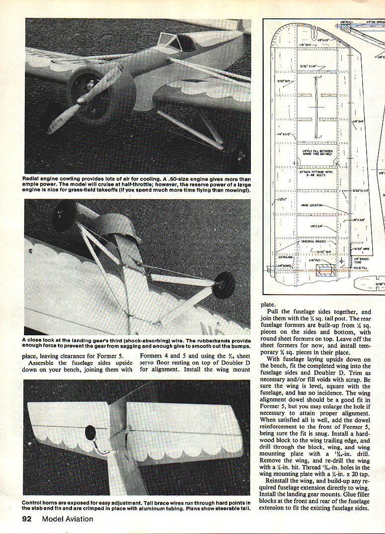
The balsa landing gear fairing is glued on with CyA (cyanoacrylate). The gear is a three‑wire system with the twin axle held by rubber bands to provide some extra give for hard landings. The entire assembly is secured to the hardwood gear blocks with screws and straps.
Pull the fuselage sides together and join them with the 1/4‑sq. tail post. The rear fuselage formers are built up from 1/4‑sq. pieces on the sides and bottom, with round‑sheet formers on top. Leave off the sheet formers for now and install temporary 1/4‑sq. pieces in their place.
With the fuselage laying upside down on the bench, fit the completed wing into the fuselage sides and Doubler D. Trim as necessary and/or fill voids with scrap. Be sure the wing is level, square with the fuselage, and has no incidence. The wing‑alignment dowel should be a good fit in Former 5, but you may enlarge the hole if necessary to attain proper alignment. When satisfied, add the dowel reinforcement to the front of Former 5, being sure the fit is snug.
Install a hardwood block to the wing trailing edge, and drill through the block, wing, and wing mounting plate with a 3/16‑in. drill. Remove the wing and re‑drill the wing with a 1/8‑in. bit. Thread 1/4‑in. holes in the wing mounting plate with a 1/4‑in.‑20 tap.
Reinstall the wing and build up any required fuselage extension directly to the wing. Install the landing gear mounts and glue filler blocks at the front and rear of the fuselage extension to fit the existing fuselage sides. Install the fuselage bottom sheeting.
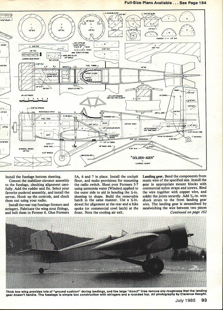
Cement the stabilizer‑elevator assembly to the fuselage, checking alignment carefully. Add the rudder and fin. Select your favorite pushrod assembly and install the servos. Hook up the controls and check them out using your radio.
Install the rear top fuselage formers and stringers. Fabricate the wing strut fittings and bolt them to Former 6. Glue Formers 5A, 6, and 7 in place. Install the cockpit floor and make provisions for mounting the radio switch. Sheet over Formers 5–7 using ammonia water (Windex) applied to the outer side to aid in bending the 1/4‑in. sheeting to shape. Build the removable hatch in the same manner. Use a 1/4‑in. dowel for alignment at the rear and a bike spoke (or commercial cowl latch) at the front. Note the cooling air exit.
Landing Gear
- Bend the components from music wire of the specified size.
- Install the gear in the appropriate mount blocks with commercial nylon straps and screws.
- Bind the wire together with copper wire and solder the joints securely.
- Add 1/2‑in. wire shock struts to the front landing gear wire.
- Streamline the landing gear by sandwiching the wire between two pieces of 1/16 x 1‑1/4‑in. balsa and sanding to shape.
- Install the tail wheel assembly using a commercial nylon tail wheel bracket.
Cowl and Struts
Cowl:
- Build the cowl by joining Formers 2 and 3 with 1/8‑in. spruce stringers.
- Cut a piece of 1/8‑in. plywood to size and soak it in water for 15 minutes.
- Roll the wet ply around the former assembly and allow it to dry overnight.
- When the ply is basically dry, glue it permanently to the former assembly with the joint over the bottom stringer.
- Add Former 1 and sand to shape.
Wing struts:
- Assemble the wing struts over the plan.
- Cut the 1/4‑in. spruce members slightly long for final fitting to the model.
- Join the spruce with plywood reinforcers and add balsa fairing stock.
- Sand to a streamlined shape.
- Attach the wing to the fuselage, fit the struts for proper length, mark, and drill the bolt holes.
Finishing/Covering
Give the model a final sanding and select your favorite covering. The original has nylon on the wing and turtledeck and silkspan over the wood parts for added strength and ease of filling wood grain. To utilize this method, proceed as follows:
- Give the entire model two coats of clear butyrate dope, sanding lightly between coats.
- Cut the nylon to approximate size and lay it on the structure. Spray the fabric with water and smooth out any wrinkles. The wet material will cling to the structure, aiding in proper placement.
- When satisfied, lift the edges of the covering and apply dope for adhesion. Smooth the cloth as you proceed. Trim excess cloth with a single‑edge razor blade.
- Apply the first coat of dope with a flat foam brush to prevent working the dope clear through the fabric. Dope must penetrate the fabric, but if allowed to soak through it will run down the backside and cause unsightly blisters.
- Silkspan may be laid in place dry over sheeted surfaces and adhered by working lightly thinned dope (75% thinner, 25% dope) through the paper to soften the dope previously applied to the structure.
- Build up a clear dope base finish until a good gloss appears (five to seven coats). Apply pigmented dope, preferably with a spray gun, to suit your fancy.
Detailing
Final touches involve installing the cockpit coaming (made from black fuel tubing or windshield wiper hose from an auto parts store) and a windshield to suit. Heavy plastic framed with paint or tape will suffice for the latter, or a metal frame can be made as desired.
Tail brace wires are made from .018‑in. control‑line cable. Drill small holes through the reinforcing dowels and thread the cable through. Anchor it under the tail wheel bracket screw heads. Form a loop secured by a short length of 1/8‑in. aluminum tubing and crimp with pliers.
Installations
Put in the radio, engine, etc., and assemble the complete aircraft. Check for balance as indicated on the plan. If ballast is needed to correct the center of gravity (CG), secure it well. Do not fly without the proper CG.
Control travel limits (measurements at the trailing edges):
- Ailerons: 1/2 in.
- Elevators: ±3/4 in.
- Rudder: 1 in. left and right
Flying
Flying the Golden Ager is pure joy. You will find it stable and docile, yet it will perform aerobatics quite well. If you are not an experienced flier, have an experienced RCer test‑hop your model for you. Low flyby passes are its greatest forte — everyone can admire it when it goes by low and slow.
Transcribed from original scans by AI. Minor OCR errors may remain.

