

GOSLOW
BRENT DANE
Flaps or landing gear too fast? Build this circuit and make 'em GOSLOW!
A simple, compact, and inexpensive circuit has been designed which can be connected in between the receiver and a control servo. It regulates the time required for full servo rotation between 2 and 20 seconds without any reduction in the servo's torque. It is a proportional device that allows the servo to be positioned anywhere within the allowed servo travel and fully supports the adjustable travel volume that is available on most radio systems.
Today's modern servos are reliable, powerful, smooth, and fast. Boy, are they fast! The time required for a full 90° of rotation typically varies between about 1/5 and 1/4 second. This is good news for control functions such as ailerons, elevator, and rudder where the quick response results in improved aircraft control. However, for other control functions such as landing gear retraction and flap extension, the speed of servo motion is less critical. In fact, it is often desirable to slow the control of these components for increased realism and in some cases, improved performance.
The sudden lowering of the flaps to their full setting can cause the airplane to pitch upward and balloon, adding unwanted altitude. If the flaps are lowered slowly and steadily as the model's airspeed is allowed to gradually bleed off, the undesirable sudden nose-up attitude can be prevented.
One solution is to control the flaps, as is often done with a proportional channel which provides continuous adjustment. However, the typical modeler is not looking for one more coordinated control to make during the critical landing approach.
Another common problem encountered is that of servo-actuated retractable landing gear that operates too quickly. Here, the objection is primarily related to aesthetics (it doesn't look good) although the extension or retraction of the gear sometimes does result in noticeable vertical trim change in the airplane.
This problem is partly alleviated by the use of a specially designed 180° landing gear servo that travels somewhat more slowly. However, these servos are significantly more expensive than regular servos and are still quite fast compared to the 5–10 second landing gear motion that provides the best realism.
Another objection is that the landing gear servo is not a proportional device; it moves between two fixed endpoints that cannot be set by the adjustable travel volume (ATV) controls on your transmitter. Landing gear installation is greatly simplified by being able to precisely adjust the servo travel to assure reliable gear locking in the up and down position without overdriving the retract mechanism and stalling the servo.
What is needed is a magic box that sits between the servo and the receiver, to take control input from the user and accurately pass it on to the servo, but regulate the maximum rate that the servo position could change. It should slow the servo by regulating the control signal to the servo — not by reducing the electrical power to the servo motor. This would be equivalent to slowly turning a proportional control knob on the transmitter from one position to another.
GOSLOW plugs in between the servo and the receiver, draws very little power, and has only one adjustment which controls the speed between about 2 and 20 seconds for full rotation. The finished circuit is only about 1.25 x 1.75 inches.
I have specially designed the circuit to use very common components which are easily found at a local electronics supply and whose availability should be well assured into the foreseeable future. This device is not just for landing gear or flap control; applications could also include the opening and closing of gear doors, bomb bay doors, or sliding or hinged cockpit canopies.
TABLE 1
- Qty: 1 — 33 ohm resistor — Part #: 271-007 — # packages: 1
- Qty: 1 — 1k resistor — Part #: 271-1321 — # packages: 1
- Qty: 3 — 10k resistor — Part #: 271-1335 — # packages: 1
- Qty: 1 — 33k resistor — Part #: 271-1341 — # packages: 1
- Qty: 8 — 47k resistor — Part #: 271-1342 — # packages: 2
- Qty: 1 — 220k resistor — Part #: 271-1350 — # packages: 1
- Qty: 1 — 1M resistor — Part #: 271-1356 — # packages: 1
- Qty: 1 — 100k horizontal-mount potentiometer — Part #: 271-284 — # packages: 1
- Qty: 2 — 470 pF ceramic disk capacitor — Part #: 272-125 — # packages: 2
- Qty: 2 — 0.01 µF PC-mount capacitor — Part #: 272-1065 — # packages: 2
- Qty: 2 — 22 µF radial-lead electrolytic capacitor — Part #: 272-1026 — # packages: 2
- Qty: 1 — 220 µF radial-lead electrolytic capacitor — Part #: 272-956 — # packages: 1
- Qty: 2 — MPS2222A NPN transistor — Part #: 276-2009 — # packages: 2
- Qty: 1 — 556 dual timer — Part #: 276-1728 — # packages: 1
- Qty: 1 — LM324 quad op-amp — Part #: 276-1711 — # packages: 1
TABLE 2
Resistors
- R1 — 33 ohm
- R2 — 10k
- R3 — 47k
- R4 — 10k
- R5 — 47k
- R6 — 47k
- R7 — 47k
- R8 — 47k
- R9 — 47k
- R10 — 220k
- R11 — 1k
- R12 — 100k trim pot
- R13 — 10k
- R14 — 33k
- R15 — 220k
- R16 — 47k
- R17 — 47k
- R18 — 1M
Capacitors
- C1 — 22 µF
- C2 — 470 pF
- C3 — 470 pF
- C4 — 470 pF
- C5 — 220 µF
- C6 — 0.01 µF
- C7 — 22 µF
- C8 — 0.01 µF
Transistors
- Q1 — MPS2222A
- Q2 — MPS2222A
Integrated Circuits
- IC1 — LM324
- IC2 — 556
TABLE 3
Manuf. — + voltage — - voltage — Signal
- Airtronics — black/red — black — black
- JR — red — brown — orange
- RCD/Hitec — red — black — yellow
- Futaba — red — black — white
To explain how the GOSLOW circuit works, a brief description of the control signals to a servo must be given.
Three wires connect each servo to the receiver. The first two supply the plus and minus voltage from the battery pack and are often red and black, respectively. The third wire carries pulses that direct the motion of the servo. These positive pulses occur at a rate of about 60 per second and vary in width from about 1–2 ms (milliseconds, or thousandths of a second). A pulse width of 1 ms sends the servo output to the limit of rotation in one direction and 2 ms to the limit in the other. For example, the pulse width supplied to a servo near the center position is approximately 1.5 ms.
The GOSLOW takes the input pulse train from the receiver and generates a new pulse train on the output. It uses a feedback loop to make the width of the incoming and outgoing pulses exactly the same.
When the width of the incoming pulses changes, however, the width of the output pulses does not immediately change but slews at a constant rate, adjustable by a potentiometer on the board, until the pulse widths match once again. It is a truly proportional device since the servo output can be positioned to any specified angle within the allowed range of travel.
The GOSLOW circuit is based on the common 555 timer chip. Actually, the 556 version is used, which is two independent 555s in a single 14-pin package. The timers are configured as one-shot pulse generators; that is, they produce a single output pulse of a specified duration when supplied with a trigger pulse.
The second integrated circuit (IC) used in the GOSLOW is the LM324 quad operational amplifier. It contains four independent op-amps, has very low power consumption, and is designed to operate from a single-sided power source such as a simple battery pack.
Servo motors tend to draw current in many small "gulps" lasting only 1–2 milliseconds each. This places a small ripple on the receiver battery voltage when a servo is in motion. Although the GOSLOW will continue to work over a wide battery voltage range, these rapid voltage fluctuations can interfere with its proper operation.
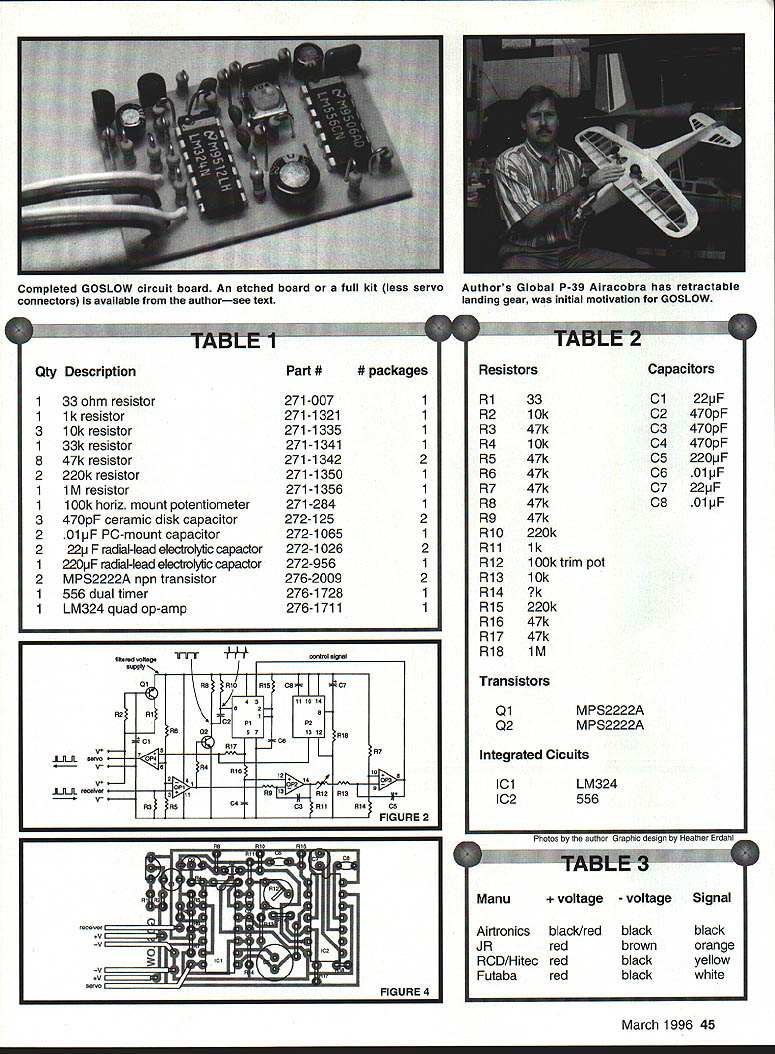
Referring to the schematic shown in Fig. 2, resistor R2, capacitor C1, and transistor Q1 form a filtered voltage source which supplies the entire circuit and suppresses any rapid voltage flutter. Resistor R1 acts as a current limit to protect Q1 in the case of an accidental short circuit.
So what about the going slow part?
The pulse width information must be converted to a DC voltage proportional to the pulse width. The GOSLOW accomplishes this, changes the DC voltage at a controlled rate determined by the user-adjustable potentiometer, and then converts the slowly changing voltage back into pulses of the appropriate width to drive the servo.
Notice that in between the output of op-amp 2 and the control pin is op-amp 3, which is configured as a linear voltage ramp generator. Capacitor C5 is charged (or discharged) at a constant current, resulting in a linearly changing voltage on the output of op-amp 3.
The variable resistor R12 (actually a potentiometer) adjusts the rate of voltage change, allowing it to be slowed to about 20 seconds for the full servo motion. Resistor R13 sets a lower limit of about 2 seconds.
The output of pulse generator P1 is sent to the servo. It is buffered through op-amp 4 in the same way the receiver input was buffered by op-amp 1. This isolates the pulse generator from the servo load and completely protects the GOSLOW output against short circuits.
When the circuit first receives power, the control signal to P1 starts out at a low voltage before capacitor C5 is fully charged, initially resulting in very short output pulses. Although the feedback loop immediately takes control and adjusts the pulse width to match whatever width is incoming from the receiver, it can only make this adjustment at the rate the user has chosen by the setting of potentiometer R12. This means that immediately after the receiver in the airplane is powered up, unwanted servo motion can occur.
Pulse generator P2 solves this problem by creating a 25-second delay, determined by R18 and C7, when the circuit first receives power. The discharge pin 13 of P2 holds the pulsed output low during this delay. Therefore, servo motion is disabled for the first 25 seconds after the receiver is powered up, preventing an unexpected servo glitch.
CONSTRUCTION
An important goal was to be able to completely build GOSLOW from components that can easily be purchased at an electronics supply such as Radio Shack. Table 1 is a complete parts list, with the Radio Shack catalog numbers and quantities required. Note that the resistors are sold in packets of 5 and some capacitors in packets of 2 so that the builder will find ample parts for several of the devices described here.
Figure 3 is an exact-size pattern for the printed circuit board. The best way, I believe, of making this board is with a product called Press-n-Peel. It is a blue plastic film that can be run through a conventional photocopier.
(Press-n-Peel is manufactured by Techniks, Inc. and can be ordered from All Electronics Corp., Van Nuys, CA 91411; Tel: (818) 997-1806. All Electronics Corp. is also a good source of the electronic components required for the GOSLOW.)
Following the instructions supplied with the film, the image in Fig. 3 should be copied onto the dull side. It is then ironed onto a copper-clad board (Radio Shack 276-1499) using a household or your airplane film sealing iron.
When experimenting to find the best temperature, I found it useful to securely tape the film to the board along one edge. I could then carefully peel back a small portion to test the adhesion of the pattern to the board. If the transfer was incomplete, the film was let back down and additional pressure at a higher temperature was used.
After successful image transfer, the board is etched in a solution of ferric chloride (Radio Shack 276-1535) for about 30 minutes or until all unwanted copper is gone. Note that the blank board is two-sided, so the copper will be completely removed from the back side. This board is large enough to make up to eight circuits.
After etching, the mounting holes should be drilled with a #65 bit. This is easily accomplished since the copper surrounding each hole location accurately guides the drilling.
Those interested in building a circuit but who do not want to manufacture a PC board may contact the author (address at end of article). An etched PC board is $10 plus a SASE (check or money order, please). Alternatively, a complete unassembled kit, minus servo connectors, can be obtained for $20.
Fig. 4 shows a schematic of the installation of the components onto the board. They should be inserted from the side opposite from the copper circuit pattern. Table 2 is a list of the components with their required values.
J1 is simply a wire jumper made from a leftover trimmed resistor lead. All of the resistors should be mounted vertically. Pay special attention to IC1, IC2, C1, C5, C7, Q1, and Q2, since the direction they are installed is very important. Capacitors C1, C5, and C7 should have a marked positive or negative lead.
Carefully solder the installed components to the copper circuit pattern, taking care to avoid solder bridges across gaps between the traces. Advice and/or instruction from a fellow modeler with circuit assembly experience could be useful here.
Input/output leads can be obtained by cutting a servo extension cable appropriate to your particular radio system in half. Please note that the cabling shown in Fig. 4 is for Futaba, JR, and RCD radio systems. Airtronics users should be cautioned that the V+ and V- wires should be reversed from how they are shown. Table 3 summarizes the wire color codes typically used for some common radio systems.
Installation and operation
Now the easy part! To use the GOSLOW, the circuit is simply plugged in between the receiver and the servo. I like to wrap the circuit in a layer of 1/4" latex foam held with two rubber bands and then tuck it in near the receiver.
Adjust the potentiometer on the board to the desired servo speed (clockwise = faster) and you're ready to go!
Remember that for 25 seconds after you switch on the receiver, no servo motion is possible. Modelers who have experience with retractable landing gear understand the importance of checking the gear switch before turning on the transmitter. This is still important with the GOSLOW; only the surprise of your airplane rocking on its belly in the dirt will come 25 seconds later!
Is this circuit really worth the effort? Just wait until you and your fellow modelers see those flaps and landing gear GOSLOW! For answers to questions or for additional information about the GOSLOW, the author can be contacted on the Internet at DANE1@LLNL.GOV.
Brent Dane 678 Crane Ave. Livermore, CA 94550
Transcribed from original scans by AI. Minor OCR errors may remain.

