
GREMLIN
Jerry Clifton
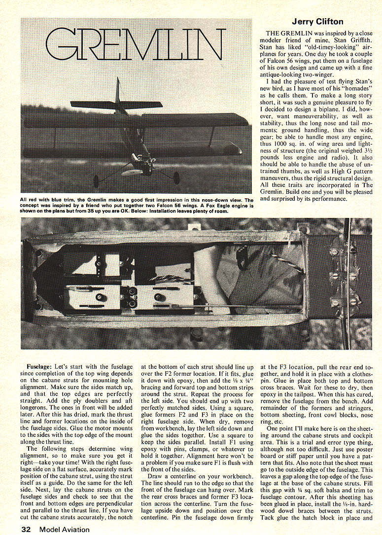
THE GREMLIN was inspired by a close modeler friend of mine, Stan Griffith. Stan has liked "old-timey-looking" airplanes for years. One day he took a couple of Falcon 56 wings, put them on a fuselage of his own design and came up with a fine antique-looking two-winger.
I had the pleasure of test flying Stan's new bird, as I have most of his "homades" as he calls them. To make a long story short, it was such a genuine pleasure to fly I decided to design a biplane. I did, however, want maneuverability, as well as stability, thus the long nose and tail moments; ground handling, thus the wide gear; be able to handle most any engine, thus 1000 sq. in. of wing area and lightness of structure (the original weighed 3½ pounds less engine and radio). It also should be able to handle the abuse of untrained thumbs, as well as High G pattern maneuvers, thus the rigid structural design. All these traits are incorporated in The Gremlin. Build one and you will be pleased and surprised by its performance.
Fuselage: Let's start with the fuselage since completion of the top wing depends on the cabane struts for mounting hole alignment. Make sure the sides match up, and that the top edges are perfectly straight. Add ply doublers and aft longerons. The ones in front will be added later. After this has dried, mark the thrust line and former locations on the inside of the fuselage sides. Glue the motor mounts to the sides with the top edge of the mount along the thrust line.
The following steps determine wing alignment, so to make sure you get it right—take your time! With the right fuselage side on a flat surface, accurately mark position of the cabane strut, using the strut itself as a guide. Do the same for the left side. Next, lay the cabane struts on the fuselage sides and check to see that the front and bottom edges are perpendicular and parallel to the thrust line. If you have cut the cabane struts accurately, the notch at the bottom of each strut should line up over the F2 former location. If it fits, glue it down with epoxy, then add the 1/4 x 1/4 bracing and forward top and bottom strips around the strut. Repeat the process for the left side. You should end up with two perfectly matched sides.
Using a square, glue formers F2 and F3 in place on the right fuselage side. When dry, remove from the workbench, lay the left side down and glue the sides together. Use a square to keep the sides parallel. Install F1 using epoxy with pins, clamps, or whatever to hold it together. Alignment here won't be a problem if you make sure F1 is flush with the front of the sides.
Draw a centerline on your workbench. The line should run to the edge so that the front of the fuselage can hang over. Mark the rear cross braces and former F3 location across the centerline. Turn the fuselage upside down and position over the centerline. Pin the fuselage down firmly at the F3 location, pull the rear end together, and hold it in place with a clothes-pin. Glue in place both top and bottom cross braces. Wait for these to dry, then epoxy in the tailpost. When this has cured, remove the fuselage from the bench. Add the remainder of the formers and stringers, bottom sheeting, front cowl blocks, nose ring, etc.
One point I'll make here is on the sheeting around the cabane struts and cockpit area. This is a trial and error type thing, although not too difficult. Just use poster board or stiff paper until you have a pattern that fits. Also note that the sheet must go to the outside edge of the fuselage. This leaves a gap along the top edge of the fuselage at the base of the cabane struts. Fill this gap with 1/4 sq. soft balsa and trim to fuselage contour. After this sheeting has been glued in place, install the 1/16-in. hardwood dowel braces between the struts. Tack glue the hatch block in place and sand everything to shape. Top wing mounting brackets will be installed after wing assembly. Finally, if desired, you may use 1/8-in. Halco-type landing gear as shown. Just substitute a piece of 1/4 ply in place of the torsion blocks and bolt gear in place.
Wings: Construction is conventional; therefore I will dwell on key points. The bottom wing is built over the plan in a straightforward manner. However, note the panels are joined after construction.
After constructing bottom panels, a slight bevel is sanded on the root rib of the panel for the proper dihedral. Block up the tip rib. Position the panel flush along the edge of the bench; use a block sander to sand the bevel using the edge of the workbench as a guide. Repeat for the other panel. This gives 1/2 inch total dihedral. Butt-join the panels with epoxy, making sure rib centerlines match. After it cures, cut away the center rib as shown.
Servo box: Add 3/32 ply braces front and rear as shown; these also serve as the front and rear faces of the servo box. When done, add center sheeting; cut the sheeting to fit the center. Because of the shallow dihedral angle, it isn't necessary to... Just pin down dry, cut out the servo box, add front 1/4 dowel, glue cap-strips, install torque rods and ailerons. Tips and the top wing are built similarly except for hold-down nut blocks and no dihedral on the plan.
Gremlin
sand everything to shape. The top wing mounting brackets will be installed after wing assembly.
Finally, if desired, you may use a 15-in. Halco-type landing gear in place of the one shown. Just substitute a piece of 1/4" ply in place of the torsion blocks and bolt the gear in place.
Wings: Construction is conventional, therefore I will dwell only on key points. The bottom wing is built over the plan and is straightforward. However note that the panels are joined after construction and not during it!
After constructing the bottom panels, a slight bevel is sanded in the root rib of each panel for proper dihedral. Block up the tip rib 1/2 inch to do this. Position the panel flush along the edge of your bench. Then, with a block sander, sand in the bevel using the edge of the workbench as a guide. Repeat for the other panel. This gives one inch total dihedral. Butt join the panels with epoxy making sure the rib centerlines match. After this cures, cut away the center rib as shown for servo box. Add the 3/32" ply braces front and rear as shown. These also serve as the front and rear servo box faces. This done, add center sheeting. Do not cut the sheeting in the center. Because of the shallow dihedral angle it isn't necessary. Just pin it down. When dry, cut out servo box, add the front 1/4" dowel, glue on cap-strips, install torque rods, ailerons and tips.
The top wing is built similarly except for the hold-down nut blocks and no dihedral. The plans show the necessary changes to be made. Note that the interplane strut boxes are on the bottom of the top wing.
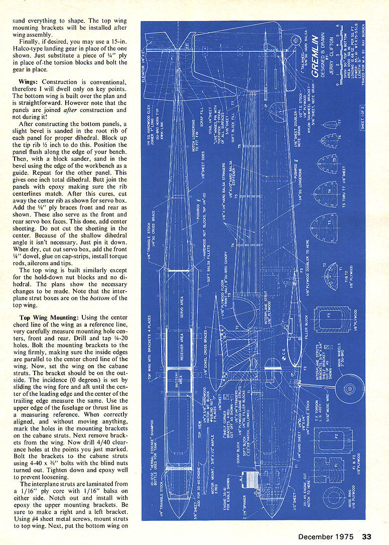
Top Wing Mounting: Using the center chord line of the wing as a reference line, very carefully measure mounting hole centers, front and rear. Drill and tap 4-40 holes. Bolt the mounting brackets to the wing firmly, making sure the inside edges are parallel to the center chord line of the wing. Now, set the wing on the cabane struts. The bracket should be on the outside. The incidence (0 degrees) is set by sliding the wing fore and aft until the center of the leading edge and the center of the trailing edge measure the same. Use the upper edge of the fuselage or the thrust line as a measuring reference. When correctly aligned, and without moving anything, mark the holes in the mounting brackets on the cabane struts. Next remove brackets from the wing. Now drill 4/40 clearance holes at the points you just marked. Bolt the brackets to the cabane struts using 4-40 x 3/8" bolts with the blind nuts turned out. Tighten down and epoxy well to prevent loosening.
The interplane struts are laminated from a 1/16" ply core with 1/16" balsa on either side. Notch out and install with epoxy the upper mounting brackets. Be sure to make a right and a left bracket. Using #4 sheet metal screws, mount struts to top wing. Next, put the bottom wing on
Gremlin
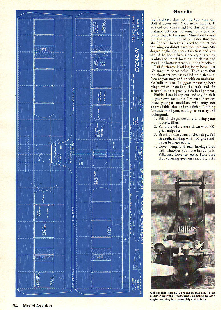
the fuselage, then set the top wing on. Bolt it down with 1/4-20 nylon screws. If you did everything right to this point, the distance between the wing tips should be pretty close to the same. Mine didn't come out too close! I found out later that the shelf corner brackets I used to mount the top wing on didn't have the necessary 90-degree angle. So check this first and you should be home free. Once equal spacing is obtained, mark location, notch out and install the bottom strut mounting brackets.
Tail Surfaces: Nothing fancy here. Just 1/4" medium sheet balsa. Take care that the elevators are assembled on a flat surface or you may end up with an undesirable built-in turn. I suggest mounting both wings when installing the stab and fin assemblies as it greatly aids in alignment.
Finish: I could go on and say finish it to your own taste, but I'm sure there are those younger modelers who may not know of this tried and true finish. Nothing fantastic mind you, but it goes on easy and looks good.
- Fill all dings, dents, etc. using your favorite filler.
- Sand the whole mess down with 400-grit sandpaper.
- Brush on two coats of clear dope, full strength, sanding with 400-grit sandpaper between coats.
- Cover wings and rear fuselage area with whatever you have handy (silk, Silkspan, Coverite, etc.). Take care that covering goes on smoothly with
a minimum of wrinkles, then fill the grain with 50 percent thinned clear dope. About four coats should do it.
- Spray on two coats of your favorite color. Add the trim.
This method provides a light finish but it is a trifle time-consuming, so, if you desire, use Monokote, Solarfilm or Flitecoat.
Flying: Now comes the fun part—flying!
Be sure the C.G. is where it is shown on the plans. While not overly sensitive to C.G. placement, this position seems about right.
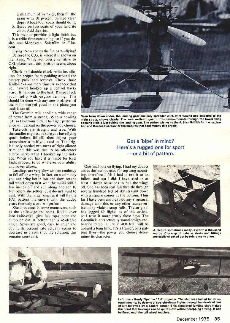
Check and double check radio installation for proper foam padding around the battery pack and receiver. Check those Kwik-links one more time. Also check that you haven't hooked up a control backward. It happens to the best! Range check your radio with engine running. This should be done with any new bird, even if the radio worked good in the plane you took it out of.
The Gremlin will handle a wide range of power from a strong .35 to a howling .61, so take your pick. The flight performance will depend on the power you choose.
Take-offs are straight and true. With the smaller engines, be sure you have flying speed before lift-off, then adjust your transmitter trim if you need to. The original only needed two turns of right aileron trim and this was due to an off-center aileron servo when I hooked up the linkage. When you have it trimmed for level flight proceed to do whatever your ability and power allows.
Landings are very slow with no tendency to fall off on a wing. In fact, on a calm day you can bring her in low and slow, set the tail wheel down first with the mains still a few inches off and run along another 10 feet before she settles. Just doesn't want to quit. With the larger engines it will fly the FAI pattern maneuvers with the added grace that only a two-winger has.
She does excel in some maneuvers, such as the knife-edge and spins. Roll it over into knife-edge, give full top-rudder and climb on out at better than a 45-degree angle. Spins are good, easy to enter and count. Its descent rate actually seems to decrease in a spin (not the rotation, this remains constant).
One final note on flying. I had my doubts about the method used for top wing mounting, therefore I felt I had to test it to its fullest, and test I did. I have tried on at least a dozen occasions to pull the wings off. She has been sent full throttle through several hundred feet of sky straight down with a square corner at the bottom. Thus far I have been unable to do any structural damage with this or any other maneuver, including violent snap rolls. The original has logged 89 flights as of this article, so I treat it more gently these days. The Gremlin is a structurally sound design and, barring radio failure at 400 feet, will be around a long time. It's a trainer, or a pattern flyer—the power you choose determines its character.
Transcribed from original scans by AI. Minor OCR errors may remain.

