
Grigg Zeppelin Works
By Walt Grigg
DURING the 1930s, there were any number of kits for building zeppelins, or, as you prefer, dirigibles. They were really Zeppelins, but here in America the latter name was used mainly because Zeppelin was a man's name and the name of an existing German firm. All these kits were inaccurate.
I became fascinated with these graceful monsters after reading Richard K. Smith's beautiful book on the Akron and Macon. A plan of 1/200th scale was obtained from the National Air & Space Museum, but this just didn't seem large enough, so I was able to get a 1/100th size from the same source. Now we had something. The real airship was 785 ft long and 132.9 ft in diameter. Big enough.
Framework
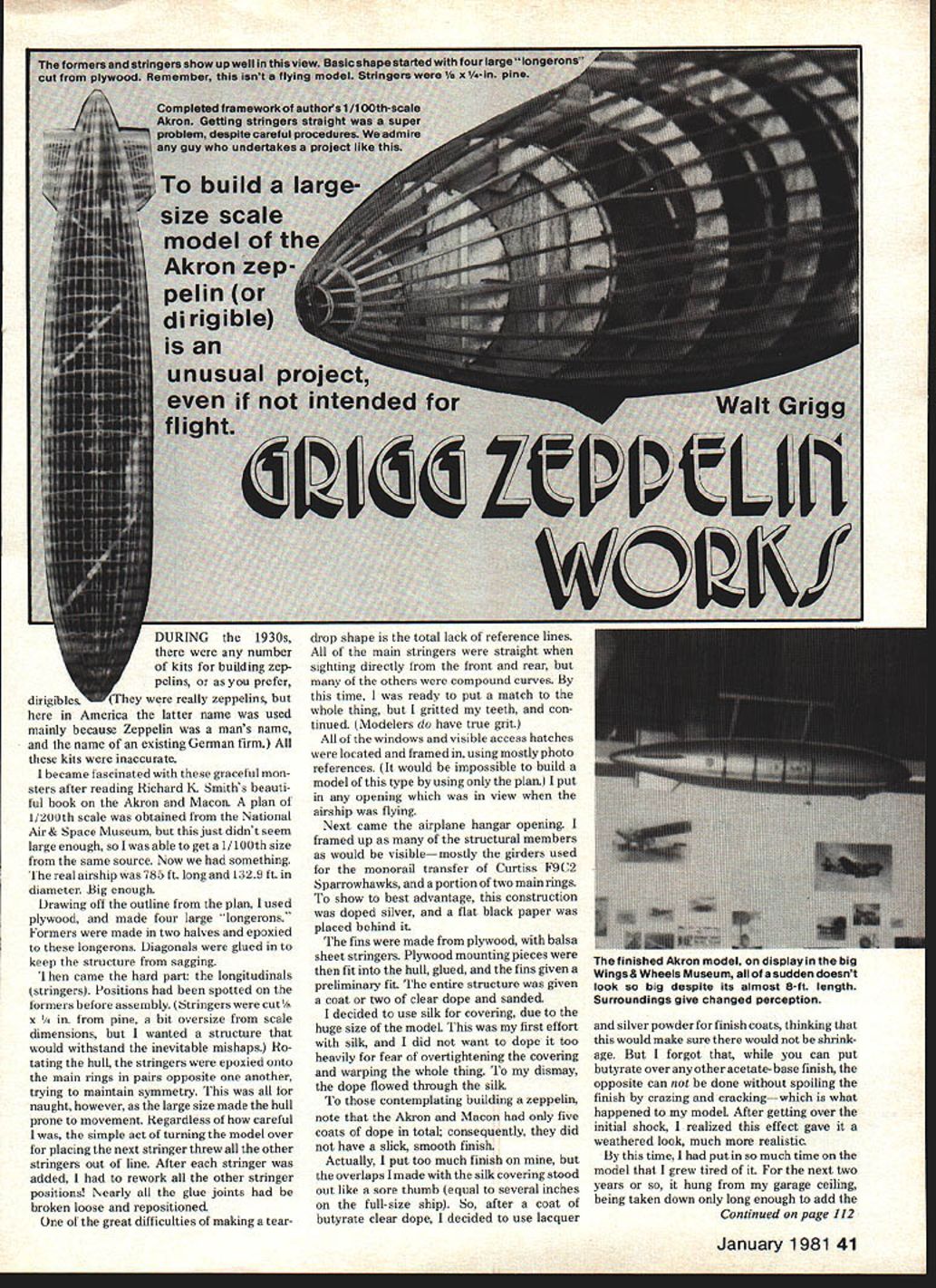
Drawing off the outline from the plan, I used plywood and made four large longerons. Formers were made in two halves and epoxied to these longerons. Diagonals were glued in to keep the structure from sagging.
Stringers and Hull
Then came the hard part: the longitudinals (stringers). Positions had been spotted on the formers before assembly. Stringers were cut 3/16 x 1/4 in. from pine, a bit oversize from scale dimensions, but I wanted a structure that would withstand the inevitable mishaps. Rotating the hull, the stringers were epoxied onto the main rings in pairs opposite one another, trying to maintain symmetry.
This was all for naught, however, as the large size made the hull prone to movement. Regardless of how careful I was, the simple act of turning the model over for placing the next stringer threw all the other stringers out of line. After each stringer was added, I had to rework all the other stringer positions. Nearly all the glue joints had been broken loose and repositioned.
One of the great difficulties of making a teardrop shape is the total lack of reference lines. All of the main stringers were straight when sighting directly from the front and rear, but many of the others were compound curves. By this time I was ready to put a match to the whole thing, but I gritted my teeth and continued. Modelers do have true grit.
Windows, Hatches, and Hangar
All of the windows and visible access hatches were located and framed in, using mostly photo references. It would be impossible to build a model of this type by using only the plan. I put in any opening which was in view when the airship was flying.
Next came the airplane hangar opening. I framed up as many of the structural members as would be visible—mostly the girders used for the monorail transfer of Curtiss F9C-2 Sparrowhawks, and a portion of two main rings. To show to best advantage, this construction was doped silver, and a flat black paper was placed behind it.
Fins, Covering, and Finish
The fins were made from plywood, with balsa sheet stringers. Plywood mounting pieces were fitted into the hull, glued, and the fins given a preliminary fit. The entire structure was given a coat or two of clear dope and sanded.
I decided to use silk for covering, due to the huge size of the model. This was my first effort with silk, and I did not want to dope it too heavily for fear of overtightening the covering and warping the whole thing. To my dismay, the dope flowed through the silk.
To those contemplating building a zeppelin, note that the Akron and Macon had only five coats of dope in total; consequently, they did not have a slick, smooth finish.
Actually, I put too much finish on mine, but the overlaps I made with the silk covering stood out like a sore thumb (equal to several inches on the full-size ship). So, after a coat of butyrate clear dope, I decided to use lacquer and silver powder for finish coats, thinking that this would make sure there would not be shrinkage. But I forgot that, while you can put butyrate over any other acetate-base finish, the opposite cannot be done without spoiling the finish by crazing and cracking—which is what happened to my model. After getting over the initial shock, I realized this effect gave it a weathered look, much more realistic.
Final Details and Display
By this time I had put in so much time on the model that I grew tired of it. For the next two years or so, it hung from my garage ceiling, being taken down only long enough to add the water-condensing radiators (four vertical black rows running up the sides of the hull) and the U.S. NAVY lettering. The main control car was carved from a single piece of basswood, with plastic windows added, and a sailor stood at the control wheel.
It probably still would have been unfinished, except that Tom Scott of Wings & Wheels Museum wanted the Akron for display. I forced myself to get back to work. The eight propeller outriggers were made from brass tubing and piano wire, each being built separately on the hull, glued and soldered together. The original ship had eight German Maybach engines of 560 hp each, which drove shafts to the geared props. These props could be swiveled up, down, fore, and aft. The Akron could move under its own power in every direction except sideways. I put plastic discs on six of the outriggers, and carved mahogany props for the other two.
The trapeze for the Curtiss fighters was made from piano wire, soldered together. The Sparrowhawk model was built from a Bachmann Boeing F4B-4 by Gary Gordon, who volunteered when he saw I still had many details to add and the deadline was fast approaching.
All in all, there are many more details that could be added, but to me this would give the model a cluttered appearance and tend to obscure the basic form.
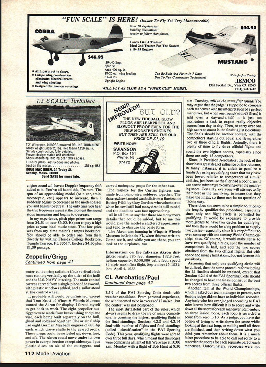
The Akron was hanging in Wings & Wheels Museum in Orlando, FL, when this was written. Come see it, and while you are there, you can look at the airplanes, too.
Full-size Akron dirigible — key information
- Length: 785 feet
- Diameter: 132.9 feet
- Helium capacity: 6,500,000 cubic feet
- Speed (max): 83 mph
- First flight: September 25, 1931
- Lost: April 4, 1933
Transcribed from original scans by AI. Minor OCR errors may remain.

