
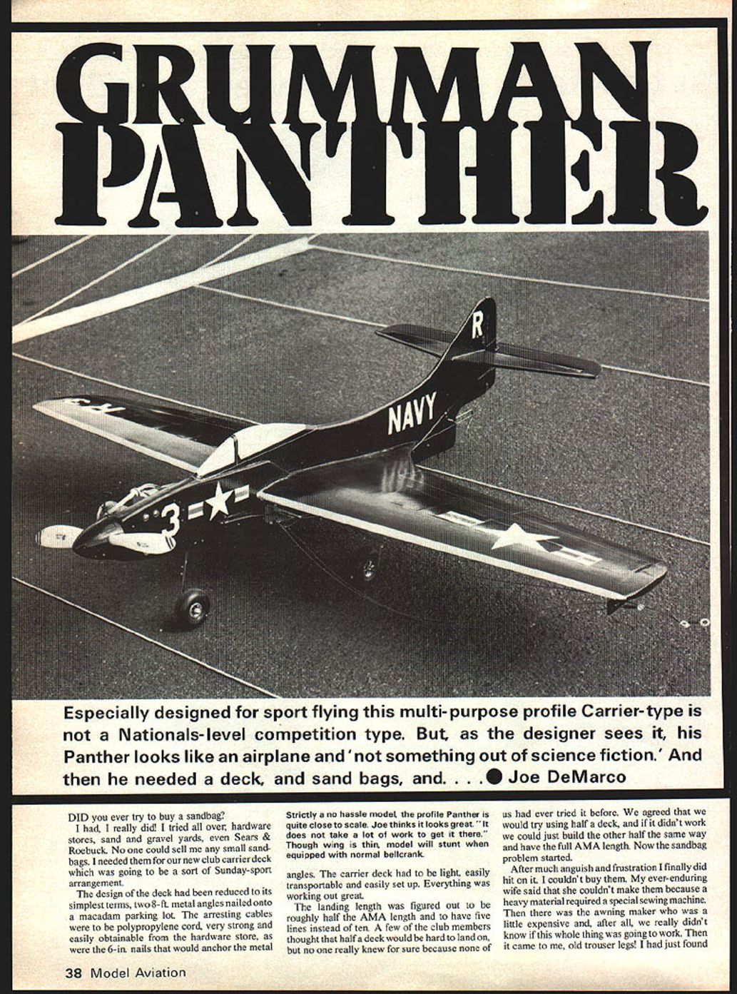
Grumman Panther
Especially designed for sport flying, this multi-purpose profile carrier-type is not a Nationals-level competition type. But, as the designer sees it, his Panther looks like an airplane and "not something out of science fiction." And then he needed a deck, and sandbags, and . . . — Joe DeMarco
Carrier deck and sandbags
Did you ever try to buy a sandbag? I had—I really did! I tried all over: hardware stores, sand and gravel yards, even Sears & Roebuck. No one could sell me any small sandbags. I needed them for our new club carrier deck which was going to be a sort of Sunday-sport arrangement.
The design of the deck had been reduced to its simplest terms: two 8-ft metal angles nailed onto a macadam parking lot. The arresting cables were to be polypropylene cord, very strong and easily obtainable from the hardware store, as were the 6-in. nails that would anchor the metal. The carrier deck had to be light, easily transportable and easily set up. Everything was working out great.
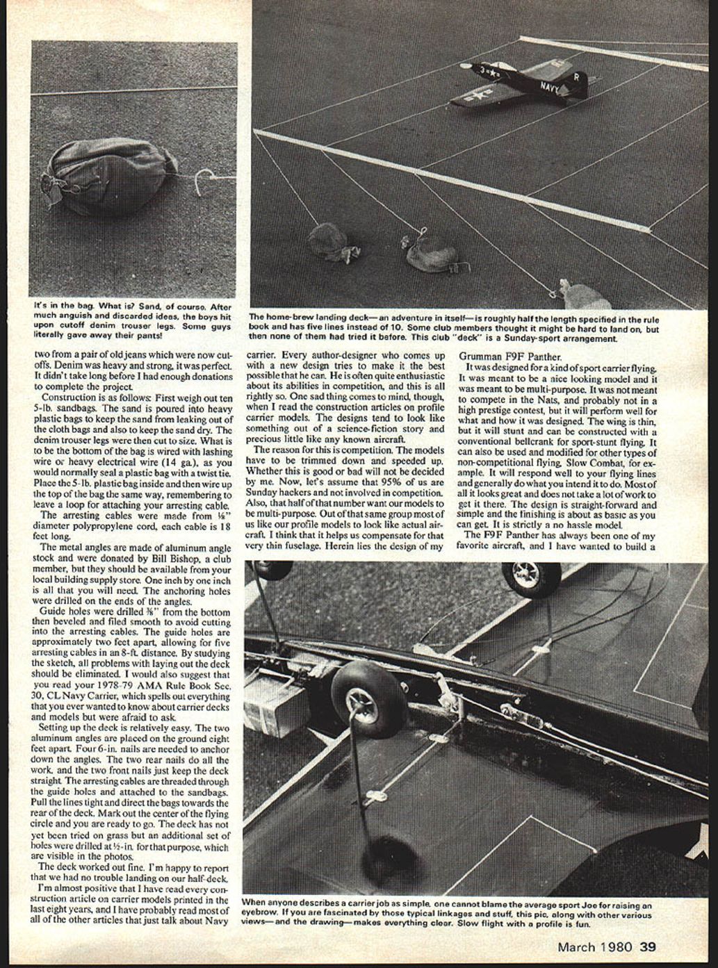
The landing length was figured to be roughly half the AMA length and to have five lines instead of ten. A few of the club members thought that half a deck would be hard to land on, but no one really knew for sure because none of us had ever tried it before. We agreed that we would try using half a deck, and if it didn't work we could just build the other half the same way and have the full AMA length. Now the sandbag problem started.
After much anguish and frustration I finally did hit on it. I couldn't buy them. My ever-enduring wife said that she couldn't make them because the heavy material required a special sewing machine. Then there was the awning maker who was a little expensive and, after all, we really didn't know if this whole thing was going to work. Then it came to me: old trouser legs! I had just found two from a pair of old jeans which were now cut-offs. Denim was heavy and strong; it was perfect. It didn't take long before I had enough donations to complete the project.
Construction is as follows:
- Weigh out ten 5-lb sandbags.
- Pour the sand into heavy plastic bags to keep the sand from leaking out of the cloth bags and also to keep the sand dry.
- Cut the denim trouser legs to size.
- Wire the bottom of the denim bag with lashing wire or heavy electrical wire (14 ga.) as you would normally seal a plastic bag with a twist tie.
- Place the 5-lb plastic bag inside and then wire up the top of the bag the same way, remembering to leave a loop for attaching your arresting cable.
The arresting cables were made from 1/8" diameter polypropylene cord; each cable is 18 feet long.
The metal angles are made of aluminum angle stock and were donated by Bill Bishop, a club member, but they should be available from your local building supply store. One inch by one inch is all that you will need. The anchoring holes were drilled on the ends of the angles.
Guide holes were drilled 3/8" from the bottom, then beveled and filed smooth to avoid cutting into the arresting cables. The guide holes are approximately two feet apart, allowing for five arresting cables in an 8-ft distance. By studying the sketch, all problems with laying out the deck should be eliminated. I would also suggest that you read your 1978–79 AMA Rule Book Sec. 30, CL Navy Carrier, which spells out everything that you ever wanted to know about carrier decks and models but were afraid to ask.
Setting up the deck is relatively easy. The two aluminum angles are placed on the ground eight feet apart. Four 6-in. nails are needed to anchor down the angles. The two rear nails do all the work, and the two front nails just keep the deck straight. The arresting cables are threaded through the guide holes and attached to the sandbags. Pull the lines tight and direct the bags towards the rear of the deck. Mark out the center of the flying circle and you are ready to go. The deck has not yet been tried on grass but an additional set of holes were drilled at 1/2-in. for that purpose, which are visible in the photos.
The deck worked out fine. I'm happy to report that we had no trouble landing on our half-deck.
Design philosophy and purpose
I'm almost positive that I have read every construction article on carrier models printed in the last eight years, and I have probably read most of all of the other articles that just talk about Navy carrier. Every author-designer who comes up with a new design tries to make it the best possible that he can. He is often quite enthusiastic about its abilities in competition, and this is all rightly so. Once again this comes to mind, though, when I read the construction articles on profile carrier models. The designs tend to look like something out of a science-fiction story and precious little like any known aircraft.
The reason for this is competition. The models have to be trimmed down and speeded up. Whether this is good or bad will not be decided by me. Now, let's assume that 95% of us are Sunday hackers and not involved in competition. Also, that half of that number want our models to be multi-purpose. Out of that same group most of us like our profile models to look like actual aircraft. I think that it helps us compensate for that very thin fuselage. Herein lies the design of my Grumman F9F Panther.
It was designed for a kind of sport-carrier flying. It was meant to be a nice looking model and it was meant to be multi-purpose. It was not meant to compete in the Nats, and probably not in a high-prestige contest, but it will perform well for what and how it was designed. The wing is thin, but it will stunt and can be constructed with a conventional bellcrank for sport-stunt flying. It can also be used and modified for other types of non-competitive flying—Slow Combat, for example. It will respond well to your flying lines and generally do what you intend it to do. Most of all it looks great and does not take a lot of work to get it there. The design is straightforward and simple and the finish is about as basic as you can get. It is strictly a no-hassle model.
The F9F Panther has always been one of my favorite aircraft, and I have wanted to build a model of it for some time. I have never had the opportunity of seeing one up close as I had with the F9F Cougar. The main difference is that the Panther had a straight wing and the Cougar's wings were swept back for better speed performance.
The early part of 1946 saw the first designs of the XF9F-1. This aircraft was to have four jet engines of 1,500 pounds of thrust each. The development of the 5,000-lb thrust Nene engine by Rolls-Royce changed Grumman's plans and it became a single-engine aircraft. This plane was designated the XF9F-2. Two models, designated G-79 by Grumman, were built and first flown in November 1947. By 1950, the Navy were using them in combat as they attacked targets in North Korea while flying from the USS Valley Forge and the USS Philippine Sea. By 1952, they were largely replaced by the Cougar F9F-6 with an 85-mph speed increase. From then on, the Panther served as a fighter-bomber until the end of the war. They did continue their military careers until 1958.
CONSTRUCTION
All cutting is done with a sharp X-Acto knife against a metal straightedge or a Dremel moto-saw. All gluing is done with aliphatic resin, Tite Bond, etc., unless otherwise noted.
Wing
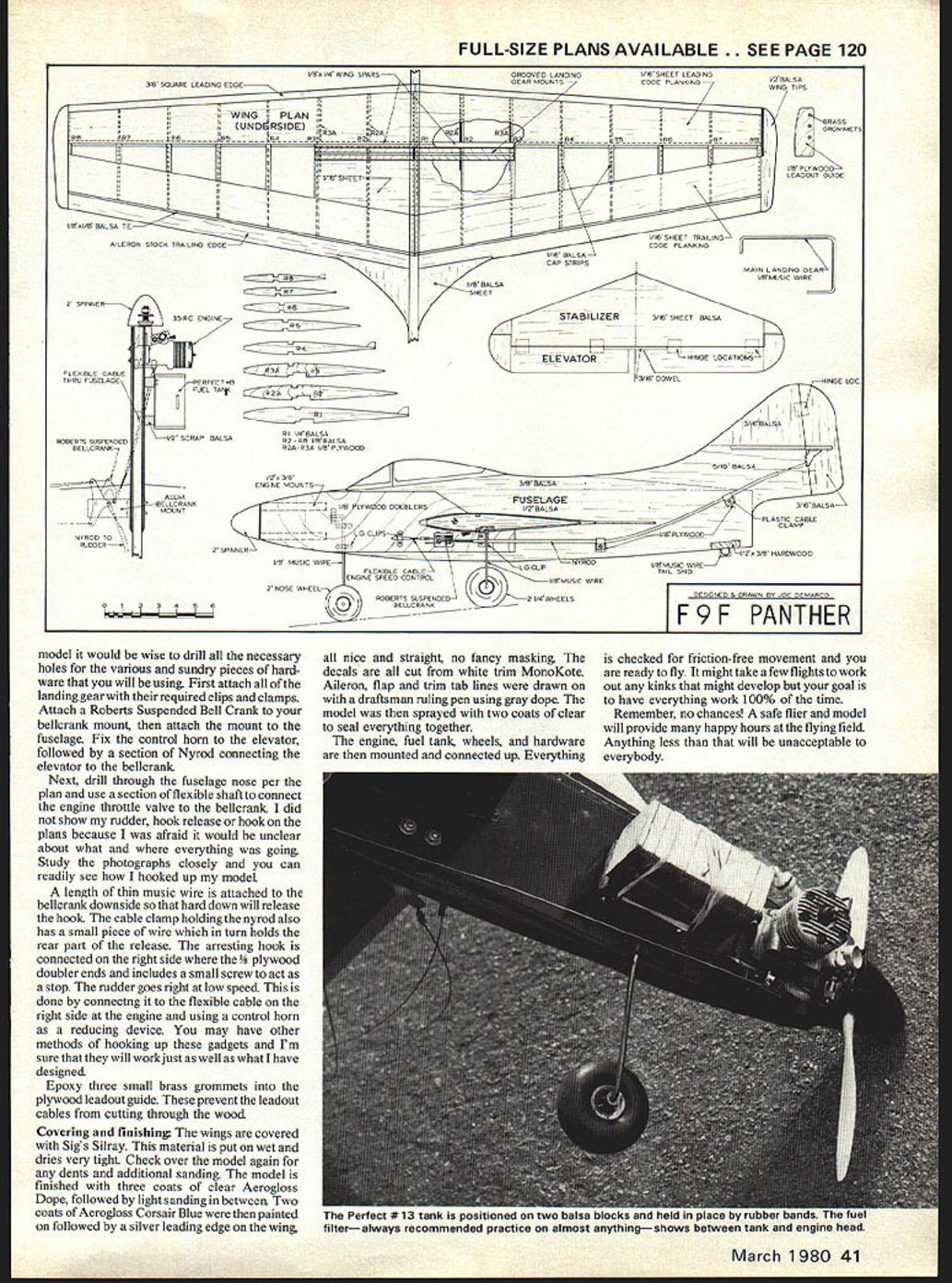
Please study the plan and note that the wing is built upside down. By doing this, the top will remain flat while the underside develops a small dihedral. Ribs R1, R4 and R8 have built-in jig devices which are trimmed off before sheeting.
Start by cutting out all of the required ribs. R1 is cut from 1/4" balsa. R2 to R8, two of each required, are cut from 1/8" balsa. Next, two each of R2A and R3A are cut from 1/8" plywood. These short ribs are then glued to ribs R2 and R3. They provide the necessary strength to hold the landing gear blocks. Sand all the ribs smooth.
Lay out the 1/8" by 3/8" balsa top wing spars by pinning them to the plan. Glue on the ribs followed by the 1/8" by 1/4" bottom wing spars. Next add the 1/8" by 1/8" trailing edge and the 1/8" by 1/4" leading edge. Epoxy in the grooved landing gear blocks. Make sure that the two blocks meet in the middle at R1. The next step is to glue on the 3/32" plywood nose sheeting and the 1/16" sheet bottom sheeting and cap strips. Be sure that the center wing is done in one piece across R1. This provides strength and you can avoid fiberglassing the center section.
Cut out the 1/8" plywood line leadout guide and glue it to the left wing tip. Remember, the wing is built with the bottom wing tip up. Next, cut out the 1/8" balsa wing tips and glue them on. Now you start your sanding. Shape the leading edge to a taper as you go. When you have finished sanding the leading edge, sheeting, wing tips, and trailing edge, you will have ended up with a fine, sleek, clean-looking wing. You may want to add wing tip weight. I didn't and noticed no penalty. The aileron stock can function as flaps and/or ailerons if you provide the proper anchoring for your hinges on the wing. Short blocks of balsa will work fine.
Stabilizer and Elevator
Cut out the stabilizer and elevator from a sheet of 3/16" balsa. The tips are cut out separately and the grain changed to be perpendicular so as to give extra strength. A 3/16" dowel is glued to the two elevator halves. After the glue has dried, use epoxy glue to hinge it to the stabilizer. Sand all the edges round and fill any dents with DAP spackling.
Fuselage
The main fuselage is made in two sections: the first from standard 1/2" by 4" stock; the second, the canopy and rear deck section, from 1/8" (but it will suffice if you have it available). Glue the two sections together, then cut out the wing slot and the engine/motor mount area.
Work into the fin section. I used a piece of 5/16" balsa for the lower part. Cut out a slot for the stabilizer then diminish to a 3/16" piece for the upper section. All these different sizes came from the scrap box and saved me an awful lot of sanding. Glue the two fin sections to the fuselage and start shaping with the sanding block. Before you shape you should have a great-looking profile. Cut out the 1/8" x 1/8" maple motor mounts. Glue in the mounts followed by the plywood doublers. Use lots of clamps and rubber bands to hold the doublers on while the glue is drying. Next, glue in the hardwood tail skid mount. When all is ready, complete the fuselage sanding followed by spackling where necessary. Glue in the wing and stabilizer. Cut out the rudder from 3/16" balsa and use epoxy to hinge it to the fin.
Bend all the landing gear from 1/8" music wire. Don't forget to include the tail skid. Next, bend the 1/8" by 1/8" aluminum bellcrank mount.
Getting it all together:
- Before finishing the model it would be wise to drill all the necessary holes for the various and sundry pieces of hardware that you will be using.
- First attach all of the landing gear with their required clips and clamps.
- Attach a Roberts suspended bellcrank to your bellcrank mount, then attach the mount to the fuselage.
- Fix the control horn to the elevator, followed by a section of Nyrod connecting the elevator to the bellcrank.
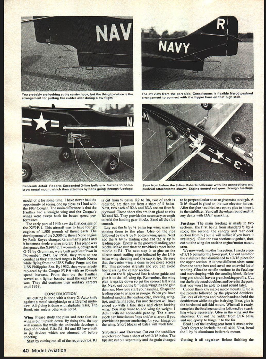
Next, drill through the fuselage nose per the plan and use a section of flexible shaft to connect the engine throttle valve to the bellcrank. I did not show my rudder, hook release or hook on the plans because I was afraid it would be unclear about what and where everything was going. Study the photographs closely and you can readily see how I hooked up my model.
A length of thin music wire is attached to the bellcrank downside so that hard down will release the hook. The cable clamp holding the Nyrod also has a small piece of wire which in turn holds the rear part of the release. The arresting hook is connected on the right side where the 3/8" plywood doubler ends and includes a small screw to act as a stop. The rudder goes right at low speed. This is done by connecting it to the flexible cable on the right side at the engine and using a control horn as a reducing device. You may have other methods of hooking up these gadgets and I'm sure that they will work just as well as what I have designed.
Epoxy three small brass grommets into the plywood leadout guide. These prevent the leadout cables from cutting through the wood.
Covering and finishing
The wings are covered with Sig's Silray. This material is put on wet and dries very tight. Check over the model again for any dents and additional sanding. The model is finished with three coats of clear Aerogloss Dope, followed by light sanding in between. Two coats of Aerogloss Corsair Blue were then painted on followed by a silver leading edge on the wing, all nice and straight—no fancy masking. The decals are all cut from white trim MonoKote. Aileron, flap and trim tab lines were drawn on with a draftsman's ruling pen using gray dope. The model was then sprayed with two coats of clear to seal everything together.
The engine, fuel tank, wheels, and hardware are then mounted and connected up. Everything is checked for friction-free movement and you are ready to fly. It might take a few flights to work out any kinks that might develop but your goal is to have everything work 100% of the time.
Remember, no chances! A safe flier and model will provide many happy hours at the flying field. Anything less than that will be unacceptable to everybody.
Transcribed from original scans by AI. Minor OCR errors may remain.

