
Grumman Skyrocket
By Allen Wulf
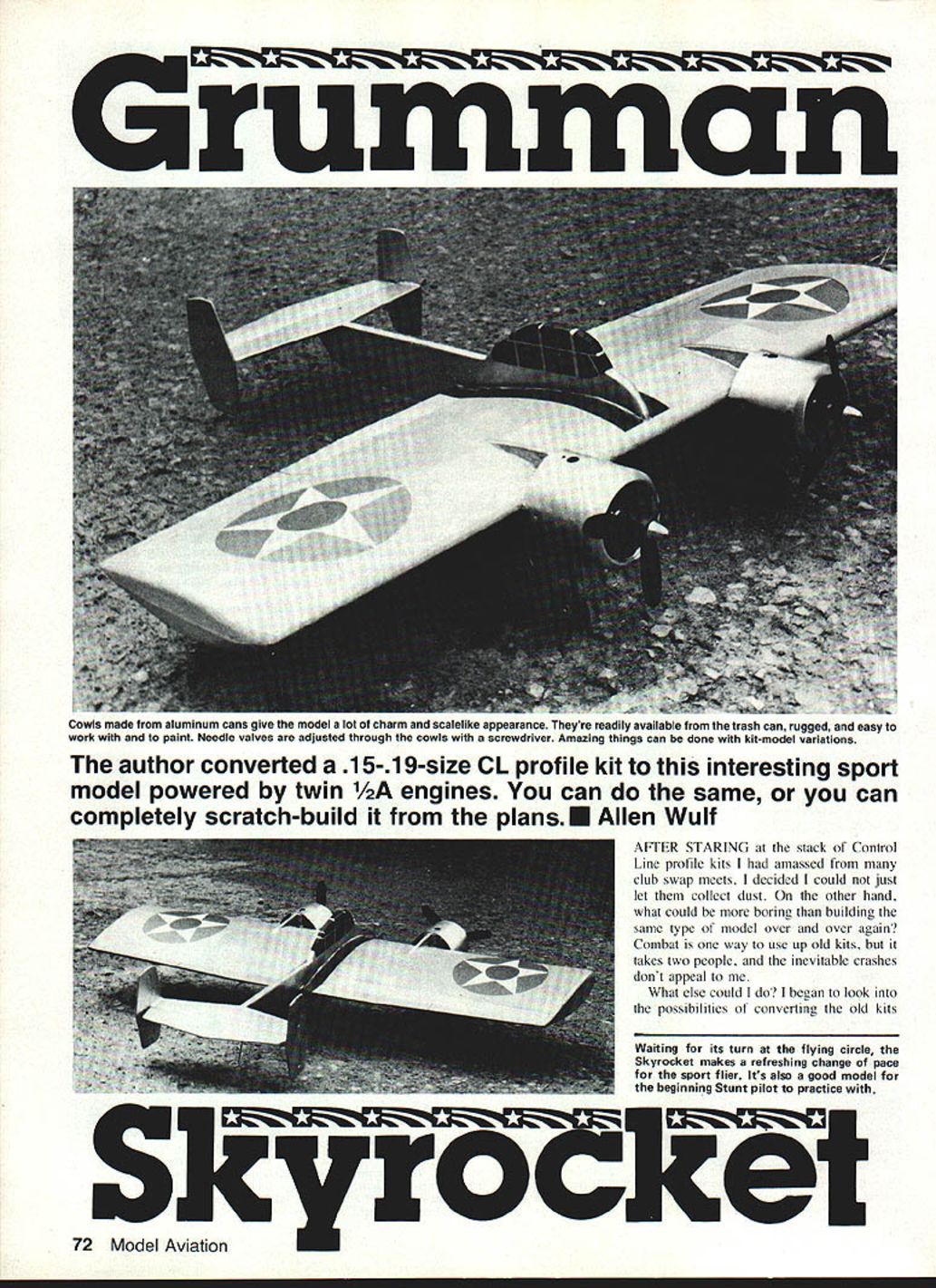
The author converted a .15–.19-size control-line (CL) profile kit into this sport model powered by twin 1/2A engines. You can do the same, or you can scratch-build it from the plans.
History and background
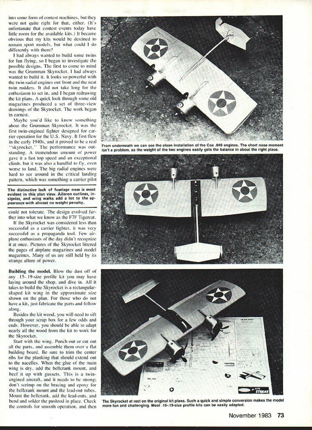
The Grumman Skyrocket was the first twin-engined fighter designed for carrier operation by the U.S. Navy. First flown in the early 1940s, it earned the nickname "Skyrocket" for its outstanding performance: high top speed and exceptional climb thanks to its powerful engines. Large radial engines forward made forward visibility in the landing pattern difficult for carrier pilots, and the design evolved into the F7F Tigercat. Although not entirely successful as a carrier fighter, the Skyrocket became a popular subject in magazines and models, retaining a distinctive, powerful appearance.
Building the model
Blow the dust off any .15–.19-size profile kit you may have in the shop or picked up at a swap meet and adapt it to the Skyrocket. A rectangular-shaped kit wing of approximately the size shown on the plan is all that’s required; if you don’t have a kit, fabricate the parts from the plans. Besides kit wood, you’ll need a few odds and ends from the scrap box, but most of the kit wood can be adapted.
Wing
- Punch out or cut all wing parts and assemble over a flat building board.
- Trim center ribs so the planking will extend into the nacelles.
- Glue the main wing and install the bellcrank mount.
- Beef up the bellcrank mount with gussets — this twin needs strong bracing; don’t scrimp.
- Epoxy the bellcrank mount and lead-out tubes. Mount the bellcrank and add lead-outs.
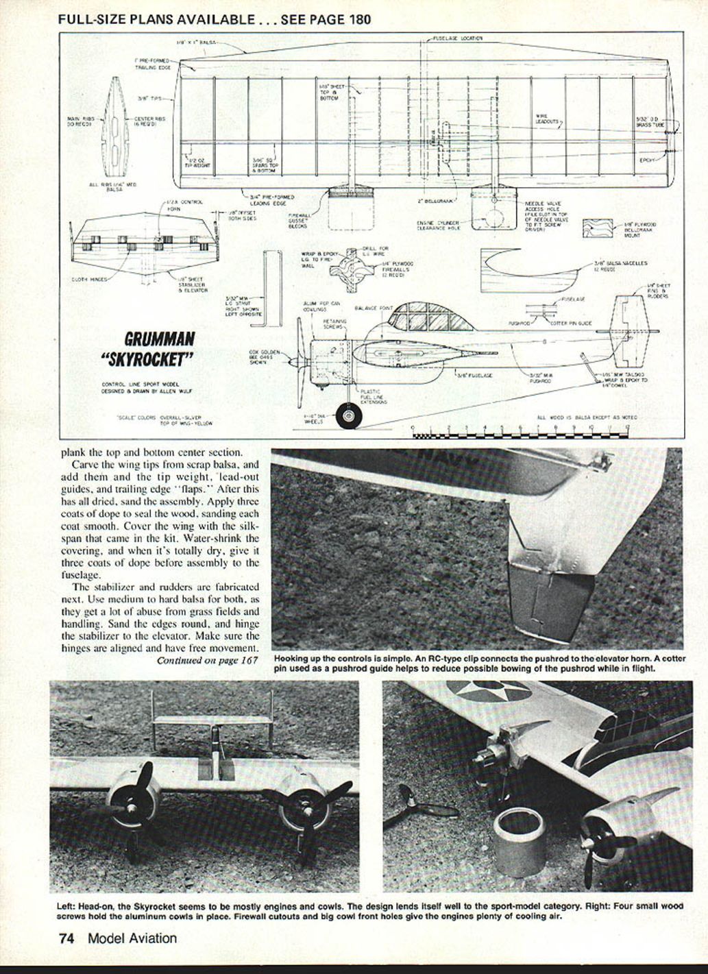
- Bend and solder the pushrod and install it. Check that controls move smoothly.
- Plank the top and bottom center section once control hardware is installed.
- Carve wing tips from scrap balsa and add tip weight.
- Install lead-out guides, trailing-edge flaps, and nacelle cutouts.
Covering
- Sand all surfaces smooth after assembly.
- Apply three coats of dope to seal the wood, sanding between coats.
- Cover the wing with the Silkspan that came with the kit and water-shrink the covering.
- When dry, give three more coats of dope before final assembly to the fuselage.
Stabilizer and rudders
- Fabricate stabilizer and rudders from medium to hard balsa for durability.
- Sand edges round and hinge the stabilizer to the elevator; ensure hinges are aligned and move freely.
- Add the control horn and secure the bolt with a drop of epoxy.
- Offset each rudder 3/16 in. outboard to keep the control lines tight in flight.
- Glue rudders to the stabilizer with epoxy or white glue; add fillets to strengthen joints.
- Verify rudders are square to the stabilizer in top and front views.
Fuselage and canopy
- Glue the fuselage together using existing kit parts.
- Use the wing plug removed earlier to form the canopy. If necessary, cut a notch for the stabilizer, aligning it with the wing centerline.
- Bend the tail skid from music wire; bind it to the dowel mounting pin with heavy thread and epoxy. Drill the fuselage hole, fill with epoxy, and insert the tail skid assembly.
- Fit the fuselage to the wing, ensuring proper alignment, and epoxy it in place.
- Add the tail assembly, let glue harden, then hook up the control system and finish the lead-outs.
Nacelles (power pods)
- Find two undented aluminum pop cans for cowls.
- Cut cans to the correct length for your engines (longer Golden Bee and Black Widow engines will fit as shown on the plans).
- Cut the remaining nacelle parts and trim plywood firewalls to fit into the aluminum cowls.
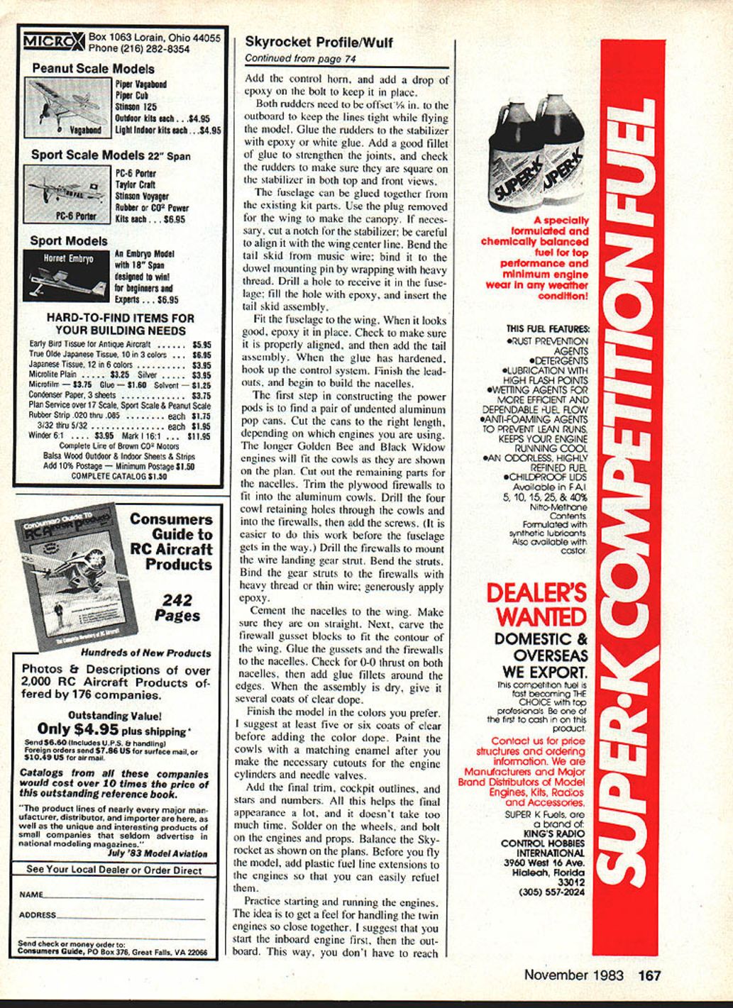
- Drill four cowl-retaining holes through the cowls and into the firewalls and add screws (easier to do before the fuselage gets in the way).
- Drill the firewalls to mount wire landing-gear struts. Bend the struts and bind them to the firewalls with heavy thread or thin wire; apply generous epoxy.
- Cement the nacelles to the wing, ensuring they are straight.
- Carve firewall gusset blocks to fit the wing contour and glue gussets and firewalls to the nacelles.
- Check for 0-0 thrust (no thrust offset) on both nacelles, then fillet glue around the edges.
- When dry, give several coats of clear dope.
Final assembly and finishing
- Paint and finish in your chosen colors. Apply at least five or six coats of clear dope before adding color.
- Paint cowls with matching enamel after cutting necessary openings for engine cylinders and needle valves.
- Add cockpit outlines, markings, and final trim to improve appearance.
- Solder on wheels and bolt on engines and props.
- Balance the model as shown on the plans.
- Add plastic fuel-line extensions to the tanks so refueling is convenient.
Engines, starting, and flying tips
- Install and practice handling the twin Cox .049 (or similar) engines mounted close together.
- Recommended starting procedure:
- Start the inboard engine first to avoid reaching over a hot prop to start the outboard engine.
- While taxiing, keep the outboard engine throttle slightly lower than the inboard to help the model track straight.
- After some taxiing and flights, adjust throttle differences for optimal takeoff and climb.
- When both engines are running at full revs, tune the needle valves until synchronized — there’s no sweeter sound than two engines in tune.
- Fly the Skyrocket on 35-ft steel control lines. The author had good results with .007 solid Speed-type lines — be sure to use steel, not cloth.
Such a quick, simple conversion makes the model fun and challenging. Most .15–.19-size profile kits can be adapted easily.
FULL-SIZE PLANS AVAILABLE. SEE PAGE 180.
Transcribed from original scans by AI. Minor OCR errors may remain.

