
Halflite
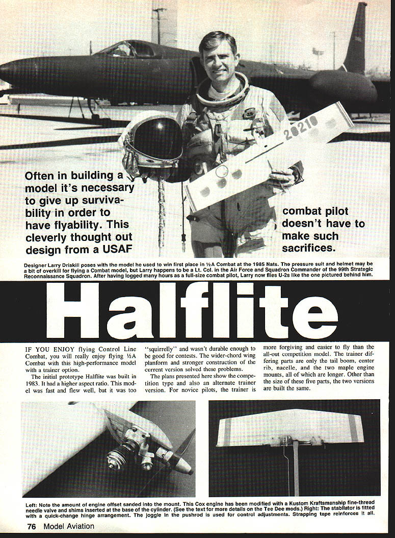
If you enjoy flying Control Line Combat, you will really enjoy flying 1/2A Combat with this high-performance model with a trainer option.
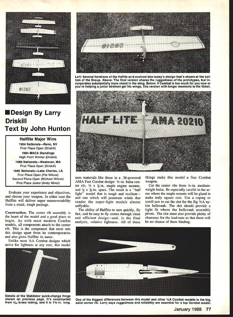
The initial prototype Halflite was built in 1983. It had a higher aspect ratio and was fast, but it proved too "squirrelly" and not durable enough for contests. The wider-chord wing planform and stronger construction of the current version solved these problems.
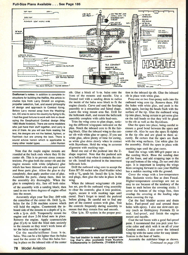
The plans presented here show the competition type and an alternate trainer version. For novice pilots, the trainer is more forgiving and easier to fly. The trainer's differing parts are only the tail boom, center rib, nacelle, and the two maple engine mounts — all of which are longer. Other than the size of these five parts, the two versions are built the same.
Construction
Center rib assembly
The center rib assembly is the heart of the model and a good place to begin. As with modern Combat models, most components attach to the center rib. This component sets the design apart from its contemporaries and gives Halflite its name.
Cut center ribs from 1/2‑in. medium‑weight balsa, being especially careful around areas where the maple mounts will be glued; make truly square cuts. Use a coping or scroll saw to cut the slot for the bellcrank. A SIG 1/2A nylon bellcrank slot should provide a tight fit. The bellcrank assembly pivots in the slot; it must also provide plenty of clearance so the lead‑outs have no chance of binding.
Note that the maple engine mounts are rounded at the back ends where they fit the center rib to prevent stress concentrations. Pre‑glue both the center rib and the engine mounts with white (aliphatic) glue thinned with one part water to three parts glue. Allow the glue to dry completely, then apply another coat. Assemble the parts, clamp them, and let the assembly dry thoroughly. When the glue is completely dry, face off both sides of the assembly with a sanding block; then sand in one to three degrees of engine offset into the mount.
Accurately align your Tee Dee .049 with the centerline of the center rib. Drill 3/32‑in. holes for the 2‑56 machine screws that will hold the engine. Countersink the inboard side of the mounts to a depth of 1/8 in. with a 5/16‑in. drill. Temporarily mount the engine and draw 2‑56 blind nuts in place. Remove the engine and apply cyanoacrylate glue (CyA) to hold the blind nuts securely to the mounts so they won't work loose after the balsa nacelle is applied.
Cut the nacelle/stiffener from 1/4‑in. balsa (this can be a bit lighter than the center rib balsa). Glue this fairing in place on the inboard side of the center rib. Glue a block of 1/8‑in. balsa onto the front of the mounts and nacelle; use a Dremel tool with a sanding drum to radius the inside of the balsa nose block to fit the engine cleanly. Carve and sand the fuselage assembly to a streamlined, faired shape, leaving the wing mount area flat. Drill for the bellcrank shaft and mount the bellcrank assembly complete with cable lead‑outs.
Materials and details
Use materials similar to those in a .36‑powered AMA Fast Combat design to produce a "half‑light" but rugged model:
- 1/2‑in. balsa center rib
- 1/2 x 3/8‑in. (or 5/16 x 1/2‑in. if shaved) maple engine mounts
- 3/16 x 3/8‑in. spars (or 1/8‑in. spars per alternate note)
- 1/4‑in. balsa nacelle/stiffener
- 1/32‑in. brass tubing for stabilator quick‑change hinge (1 in. long)
The combination of relative lightness in the right places, clean design, and strength makes the model tough, able to penetrate wind, turn quickly, fly fast, and be easy to handle.
Pre‑glue parts as noted. After final assembly sanding, sand both sides and install engine offset. Glue blind nuts in place with CyA, then double glue heavy‑load fittings with epoxy where appropriate.
Wing construction
Trim the wing cores to plan shape, noting different wingspans indicated on the plan. Notch the inboard core to fit the fairing block. Glue the inboard wing to the center rib with white glue or epoxy. If using white glue, allow plenty of time for curing, as white glue dries slowly when in contact with Styrofoam. Hold the wing in accurate alignment with masking tape.
Bend one end of the pushrod into the Z‑shape required. Note that the pushrod acts as a bellcrank stop when it contacts the center rib. Install the pushrod in the innermost bellcrank hole.
Drill the outboard wing core to accept the Estes BT‑50 rocket tube (hole/bladder tube) with a 15/64‑in. spade bit. Install the 1/4‑in. balsa end plugs, then glue the tube in place in the wing.
When the inboard wing/center rib joint has set, pre‑fit the outboard wing assembly to clear the controls; glue it into position and secure with masking tape until cured. Install the pushrod before gluing and be careful not to foul any part of the control system with glue. Test the controls frequently during assembly to ensure they remain free and smooth.
Glue 1/8‑in. ID eyelets in the proper position in the inboard tip rib and glue the inboard tip rib with white glue. Press one or two four‑penny nails into the outboard wing core to cure, remove them, fill the holes with white glue, then push the nails in again leaving the heads flush. Glue the outboard wing tip into place, making sure to get glue on the nail heads so they are glued to both the ribs and the Styrofoam.
Glue the spars into place, ensuring a good bond between the spars and center rib and a tight fit into the tip ribs. Be certain the spars are flush with the wing surfaces. Use white glue and hold spars in place with masking tape until the glue cures.
Sand the wings with 600‑grit paper on a flat sanding block. Blow the sanding dust off the foam and add strapping tape to the top and bottom of the wing — do not omit this tape, as it helps prevent the wings from swinging forward in a hard landing.
Cover the wings with a low‑temperature film such as sealant film or Fevseal. Higher‑temperature coverings can melt the foam before the covering sticks. Cover the bottom of the wing first, then overlap the covering at the leading edge when covering the top.
Cut the fuel bladder access and drain holes, and fuel‑proof and seal around these holes with epoxy. Use a slow‑cure epoxy (e.g., Hobbypoxy Formula III) to seal, fuel‑proof, and finish the engine mount and nacelle.
Controls and stabilator
Assemble the stabilator hinge as shown on the plan. The stabilator quick‑change hinge is constructed from 1/32‑in. brass tubing, 1 in. long. Remove the covering from the center body where the boom fits, and glue the boom in place with 5‑min. epoxy. When the joint has cured, install the stabilator hinge tube with CyA, being careful to align it properly so it will be level with the wing. Mount the stabilator with the 1/16‑in. wire hinge and ensure movement is free and unrestricted.
Note the dogleg bend in the stabilator rod (for throw adjustment) and the Z‑bend for the elevator horn. This simple setup is reliable and readily replaceable; stabilator adjustment is made by changing the dogleg.
Cover the stabilator with plastic film.
Fuel bladder, leadouts, and assembly tips
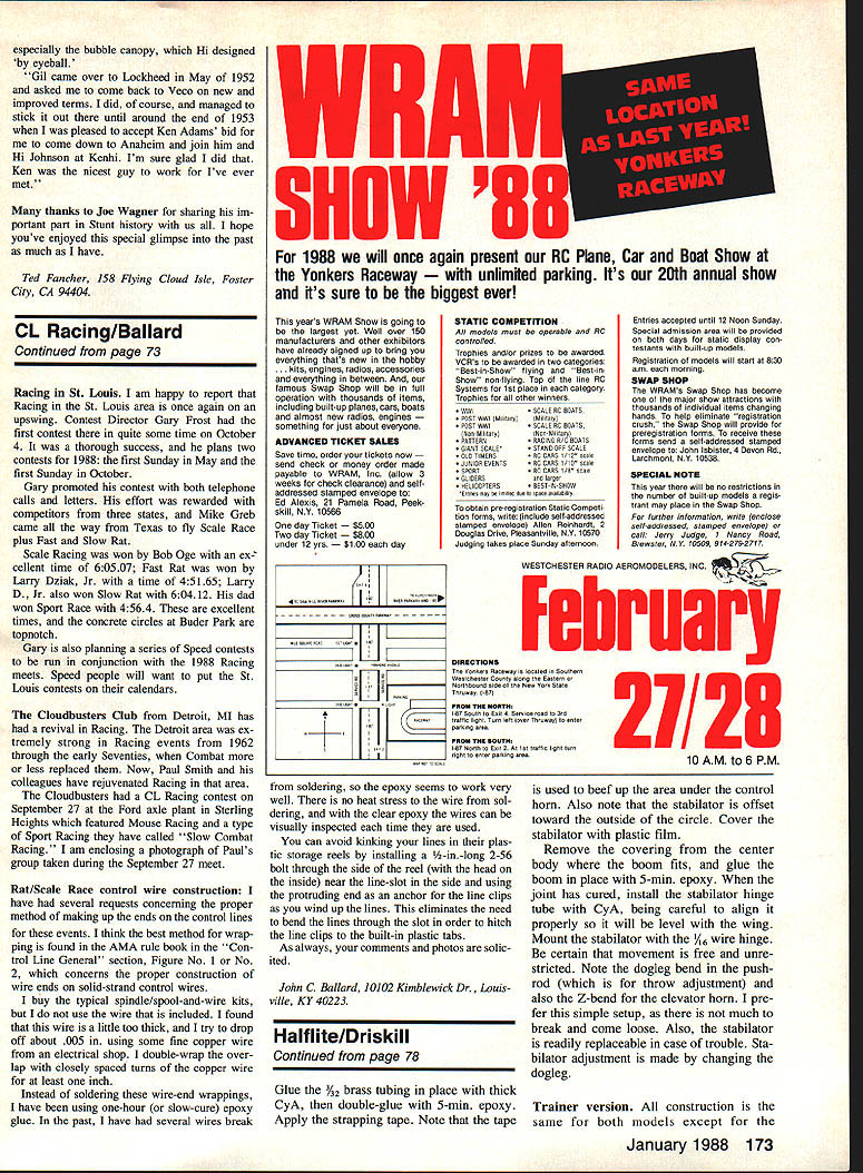
The fuel bladder is made from thin‑wall surgical tubing (Kustom Kraftsmanship part #484). Keep bladders simple by tying a knot on the back end and rubber‑banding the tubing to a length of fuel line that has a 3/32‑in. length of 3/32‑in. ID brass tubing inside to prevent collapse. The uninflated bladder needs to be only about 1/2 in. long (from crimp to rubberband) to hold fuel for four to five minutes of flight.
Glue the 3/32‑in. brass tubing in place with thick CyA, then double‑glue with 5‑min. epoxy. Apply strapping tape; the tape insulates the leadouts from soldering, so the epoxy adheres well and allows visual inspection of the wires.
A tip for line reels: avoid kinking lines by installing a 1/4‑in.‑long 2‑56 bolt through the side of the reel (head on the inside) near the line slot and use the protruding end as an anchor for the line clips as you wind up the lines. This eliminates bending the lines through the slot to hitch the clips to built‑in plastic tabs.
Trainer version
All construction is the same for both models except for the trainer's longer nose and tail moments. Substitute the longer center rib, maple engine mounts, nacelle, and tail boom as shown on the plan. This results in a model that is a bit more stable but still maneuverable and fun to fly. With the long nose there is room enough for a Perfect No. 9 fuel tank if you wish to run a hard tank and suction system.
Compromises
All aircraft designs are products of compromises or tradeoffs — Halflite is no exception. You will need to balance top performance against durability.
Choices to consider:
- Wing spars:
- Spruce spars — strong but heavier.
- Balsa spars — lighter but may break.
- Balsa spars with carbon fiber reinforcement on the center eight inches — light and strong but more expensive and more difficult to build.
- Engine mounts: the 3/8 × 1/2‑in. mounts on the plan can be shaved to 5/16 × 1/2 in. and still be adequately strong but are more trouble to build.
- Wing cores: hollowing with hot‑wire techniques saves weight but reduces strength, particularly if thinned below 3/16 in. Using all three lightening choices may save about 1/2 oz but will make the model considerably less durable.
Fuel system
Fuel bladders: use thin‑wall surgical tubing (Kustom Kraftsmanship part #484). Tie a knot at the back end and rubber‑band the tubing to a length of fuel line with a short 3/32‑in. brass tubing insert to prevent collapse. An uninflated bladder about 1/2 in. long will hold fuel for four to five minutes.
Fuel: small 1/4A engines do not tolerate dirty or contaminated fuel. Use fresh fuel and filter it at least once (either coming out of the can or going into the bladder). The author has had great results with 3% nitro fuel and Cox Racing Fuel. Ensure your fuel has at least 20% oil, of which a minimum of 5% is castor oil.
Engine
The Cox Tee Dee .049 can be run stock with good results, but a few modifications improve power and reliability:
- Replace the needle valve assembly with one having a finer thread (Kustom Kraftsmanship makes a recommended needle valve assembly for Cox engines).
- Cylinder shims with a collar (available from Kustom Kraftsmanship) allow adjustable cylinder timing for optimum power — follow the shim instructions.
- Drilling out the intake venturi per Tee Dee instructions will boost power, but larger venturis make needle settings harder and increase fuel consumption with high‑nitro fuels.
- Use Cox or Globe plugs successfully. To avoid over‑compression, start with three or four copper gaskets under the glow head and adjust to obtain safe, reliable settings. Add or remove gaskets incrementally to find maximum power without starting problems or inconsistent needle settings.
Control lines
Do not use lighter lines than .012‑in. steel cable. AMA Combat rules call for 35‑ft. line length (centerline of aircraft to centerline of handle). For practice you can use longer lines (up to 40 ft.) to slow things down a bit. The trainer version flies well on 40‑ft. lines, but you may have to add extra rail for outboard wing tip weight.
Propeller
All three Nationals wins with Halflite were achieved using Cox black 5 × 3 props — they are tough, efficient, and effective on this model. Tornado 5 × 3 props also give good performance. Use a 6 × 3 prop to slow the model and improve fuel economy.
Flying and advice
The author has more than 25 years of Control Line Combat experience and over 900 combat hours as a Forward Air Control pilot. Rule No. 1 in both fields is the same: do not run into the ground.
Other axioms for CL Combat success:
- Practice — alone, with buddies, and by entering every contest you can until flying becomes second nature.
- Keep flight and ground equipment simple — minor practice troubles become major contest troubles.
- Don't sacrifice reliability or consistency for minor performance gains, especially with the engine. Combat is not a pure speed event.
- Know the ground rules — read the AMA rule book to avoid mistakes from ignorance.
Flying 1/4A Combat successfully involves hard work in many disciplines: preparation, engines, practice, etc. The Halflite design is a proven model to help build your Combat success.
Full‑size plans available: Page 186.
Transcribed from original scans by AI. Minor OCR errors may remain.

