
HANGAR 13 for 1/2A Texaco
George Niebauer
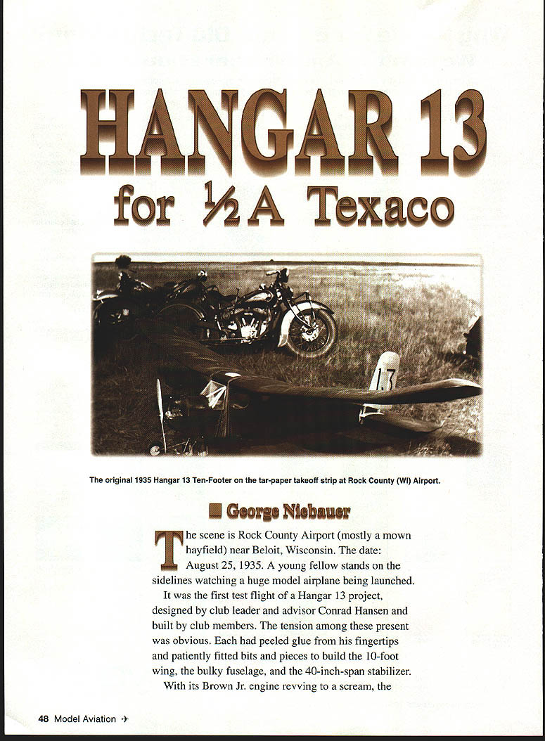
The scene is Rock County Airport (mostly a mown hayfield) near Beloit, Wisconsin. The date: August 25, 1935. A young fellow stands on the sidelines watching a huge model airplane being launched.
It was the first test flight of a Hangar 13 project, designed by club leader and advisor Conrad Hansen and built by club members. The tension among those present was obvious. Each had peeled glue from his fingertips and patiently fitted bits and pieces to build the 10-foot wing, the bulky fuselage, and the 40-inch-span stabilizer.
With its Brown Jr. engine revving to a scream, the model lumbered down the runway, each wingtip guided by the launch team members until it outran them. Slowly it wallowed into the air. Once on its way the H-13 Ten-Footer flew with noble grace. Such was the first flight of this now antique model.
The young man watched, and was bitten then and there by the model airplane "bug." I was that young man.
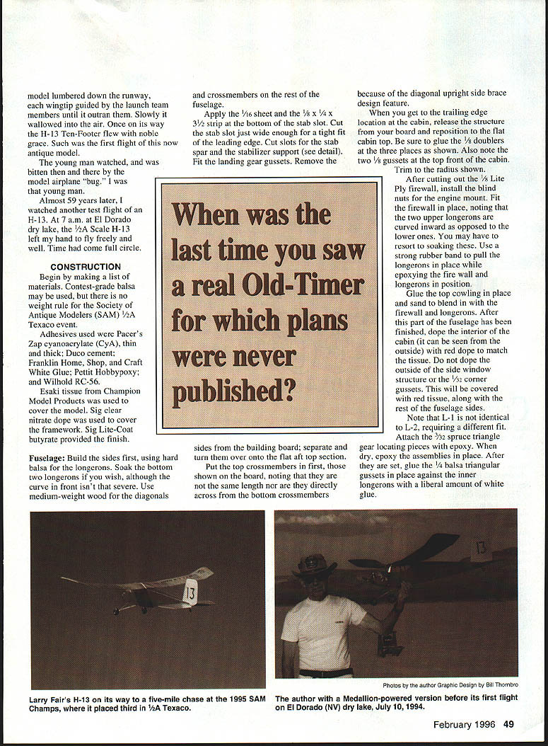
Almost 59 years later, I watched another test flight of an H-13. At 7 a.m. at El Dorado dry lake, the 1/2A Scale H-13 left my hand to fly freely and well. Time had come full circle.
CONSTRUCTION
Begin by making a list of materials. Contest-grade balsa may be used, but there is no weight rule for the Society of Antique Modelers (SAM) 1/2A Texaco event.
Adhesives used were Pacer's Zap cyanoacrylate (CyA), thin and thick; Duco cement; Franklin Home, Shop and Craft White Glue; Pettit Hobbypoxy; and Wilhold RC-56.
Esaki tissue from Champion Model Products was used to cover the model. Sig clear nitrate dope was used to seal the framework. Sig Lite-Coat butyrate provided the finish.
Fuselage: Build the sides first, using hard balsa for the longerons. Soak the bottom two longerons if you wish, although the curve in front isn't that severe. Use medium-weight wood for the diagonals and crossmembers on the rest of the fuselage.
Apply the 1/16" sheet and the 1/8" x 1/4" x 3/4" strip at the bottom of the stab slot. Cut the stab slot just wide enough for a tight fit of the leading edge. Cut slots for the stab spar and stabilizer support (see detail). Fit the landing gear gussets. Remove the sides from the building board; separate and turn them over onto the flat aft top section.
Put the top crossmembers in first, those shown on the board, noting that they are not the same length nor are they directly across from the bottom crossmembers because of the diagonal upright side-brace design feature.
When you get to the trailing-edge location at the cabin, release the structure from your board and reposition to the flat cabin top. Be sure to glue the 1/8" doublers at the three places as shown. Also note the two 1/8" gussets at the top front of the cabin. Trim to the radius shown.
After cutting out the 1/8" Lite Ply firewall, install the blind nuts for the engine mount. Fit the firewall in place, noting that the two upper longerons are curved inward as opposed to the lower ones. You may have to resort to soaking these. Use a strong rubber band to pull the longerons in place while epoxying the firewall longerons in position. Glue the top cowling in place and sand to blend in with the firewall and longerons. After this part of the fuselage has been finished, dope the interior of the cabin (it can be seen from the outside) with red dope to match the tissue. Do not dope the outside of the side window structure or the 5/32" corner gussets. This will be covered with red tissue, along with the rest of the fuselage sides.
Note that L-1 is not identical to L-2, requiring a different fit. Attach the 3/32" spruce triangle gear-locating pieces with epoxy. When dry, epoxy the assemblies in place. After they are set, glue the 1/4" balsa triangular gussets in place against the inner longerons with a liberal amount of white glue.
Carefully align the 1/16" x 1/4" x 2" birch plywood stab support with the cabin top, making certain that both surfaces are parallel. Locate and drill the holes for the wing hold-down and landing-gear positioning dowels as shown, using a tight fit. Do not glue the dowels in place.
Empennage
The stabilizer forms are 1/4" Masonite. Cut to shape, sand, and apply a generous coat of wax to the form. Cut eight pieces of 1/2" x 1/4" x 9" soft balsa for each tip, soaking the strips thoroughly in water or ammonia.
Mix a small batch of white glue and water, thinned to half normal consistency. Brush on one side of the first piece and proceed with the rest of the strips, remembering to coat only one side of the last piece. Use heavy pins or weights to hold the strips firmly against the form. Let dry for 24 hours. After the tips are dry, sand to the leading-edge dimension and taper to the trailing-edge thickness.
Pin down, CyA the 1/32" x 3/8" ribs in place. Position the trailing-edge sheeting in place with a piece of 9/64" stock. Glue the leading edge in place.
The center ribs must be a tight fit against the fuselage. Using waxed paper, position the stab onto the fuselage and fit the two innermost ribs in place. Note that the top and bottom of the four centermost ribs are reduced in thickness to allow for the 1/32" center-section sheeting.
Rudder construction is similar to that of the stab. The top lamination is formed from six strips of 1/32" x 3/16" x 6-1/2" soft balsa. The bottom lamination is formed from six strips of 1/32" x 1/4" x 4-1/2" soft balsa.
Pin the rudder spar down and shim the top and bottom with 3/32" wood. CyA the rib strips, the leading and trailing edges and the laminated tips. The rudder bottom rib is 3/32" to allow for attaching the silver rudder covering.
With the stab temporarily placed in its slot, hold the rudder spar against the stab spar and the fuselage rear, cutting a hole in the sheet on top of the fuselage to admit the leading edge. Note that it will fall a small amount to the rear of where you have it positioned because of the leading-edge angle. Do not glue the rudder and stab in place until both have been covered.
Wing
The wing construction deviates from the usual solid-spar type for lightness and strength.
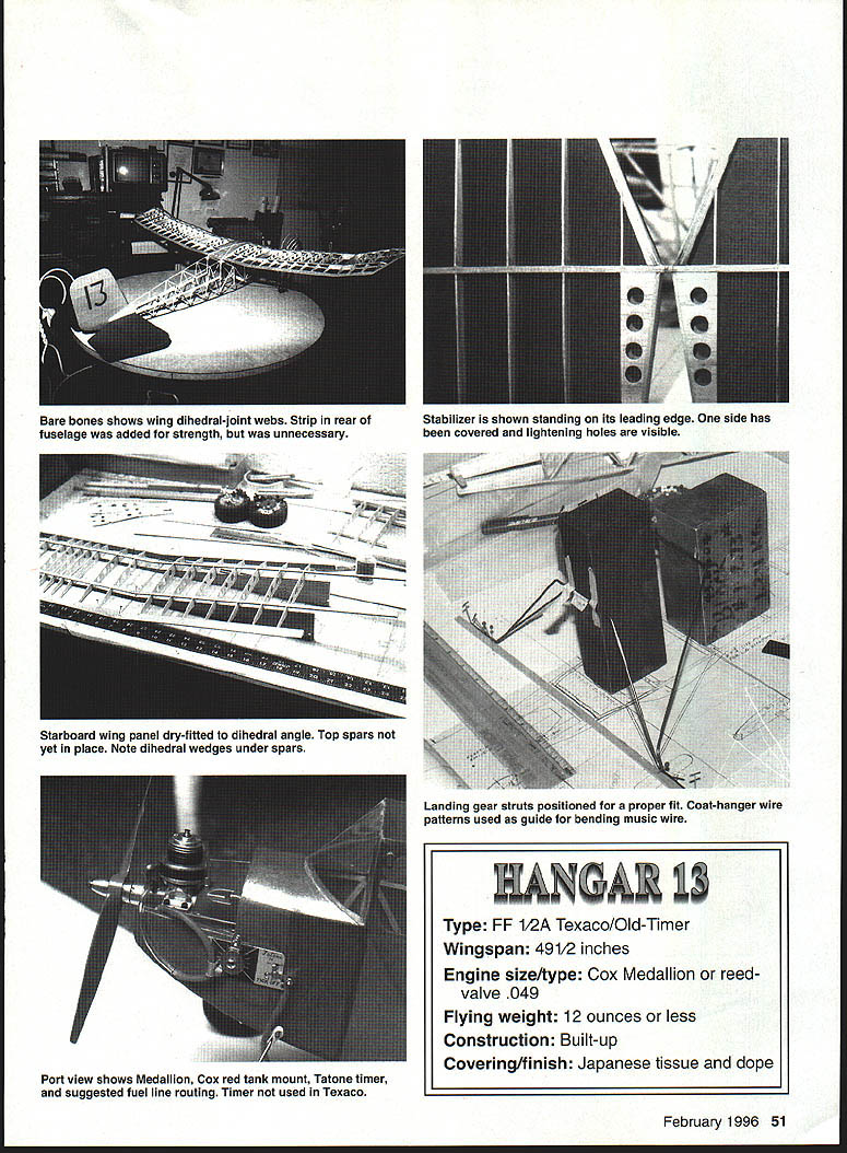
Use 1/20" medium balsa for the wing ribs. You may save some weight by cutting or punching lightening holes in the ribs (except the dihedral ribs). I found that my set of ribs was 15% lighter after the holes were cut. To further strengthen the ribs, run a bead of CyA around the inner edge of the holes. Trim 1/32" from the top only of ribs 1–3 to accept the 1/32" center-section sheeting.
Beginning with the center section, space the two spars with the notches in the rib bottom edge. Place the notched trailing edge and the rough-shaped leading edge at the juncture of the dihedral joints. By shaping the leading edge now, you will only be required to finish-sand at the dihedral joint. Be sure to leave at least 1/32" at the top of the leading edge to allow for the sheeting.
Do not cement the top spars in place at this point. The 1/8" dihedral-joint web and ribs must be positioned first.
Proceed with the starboard main panel and the tip section, again leaving out the top spars and dihedral ribs. Using the instructions for building the stab and rudder, form the wingtips using 1/32" x 1/4" x 8-1/2" soft balsa. Complete an outboard panel and tip section at this time. After shaping the laminated tips, block the wing tip up 1-1/4" with the main panel pinned down to the board.
Join the trailing edge, leading edge, and bottom spars after cutting to the proper dihedral angle. Insert the dihedral-joint webs and ribs, using white glue. Now add the two top spars joining at the dihedral ribs. Remove this starboard assembly from your board.
Build the left panels over the half-wing plan you were using; reverse the LE and TE positions, using the ribs for spar spacing. Use the dotted lines for positioning the laminated tip. Attach the panels to the center section. With a flat-bottomed airfoil this is easy.
Using clothespins, clamp a piece of scrap wood onto the dihedral rib at the dihedral dimension.
Insert the top spars into the center section, noting that they fit only 1/16" deep into the five center ribs. This will allow the sheet wood to be flush with the spar top. If you are considering flying the model in RC events, add some 1/32" vertical-grain webs between the spars in the center section and main panels.
The top and bottom spars at rib #17 should be cracked or cut to blend into rib #18 and the tip. Using the shims as shown will align the laminated tip at the leading and trailing edge. As with the fuselage, give all joints a coat (or two) of glue.
Sand the top and bottom of the wing with medium-to-fine sandpaper, and add the 1/32" sheet covering to the center section and the leading edge. Blend the leading edge into the 1/32" sheet. Wings with spars of this type are able to absorb tension and compression stresses well.
All surfaces that will be covered with tissue should receive two coats of nitrate dope thinned no more than 50%.
Landing Gear: It may be removed during repairs, it is quite crash resistant, and it makes the model easier to transport.
Before committing to bending the .078" music wire, I made patterns from coat hangers, giving me an idea of the correct angles to bend.
To line up and dry-fit the two struts, I used a few pieces of heavy iron and aluminum blocks. Placing these over the plan and using the patterns made the initial job easy. Use the same method when you are bending the music wire. Put a bit of camber and toe-in into the axles for better tracking during takeoff and landing.
Dave Brown Products has light wheels called Lectra-Lite, which can be shaped to the rounded-tire look of the original wooden wheels. They can be formed in no time after being placed in a freezer. Insert a bolt of the proper diameter and about 1-1/2" long into the axle hole with a washer at each side of the wheel and two jam nuts. Tighten enough to prevent the wheel from turning on the bolt. Put into your electric hand drill or drill press, shaping while still frozen, with coarse sandpaper over a block of wood. Refreezing may be necessary before you are finished.
Secure the wheels onto the axle with a fastener of your choice. I was able to use 1/16" Du-Bro Dura-Collars drilled out to fit the axle diameter. A #46 (.081") drill will do the trick. Du-Bro struts may be used to fasten the gear to the fuselage with small wood screws in lieu of the rubber bands.
Covering: Before attempting to cover the model, reglue all of the joints. Apply at least two coats of nitrate dope and sand with 280 or 320 paper.
I used Esaki tissue and was pleased with the results. Applied wet and using thinner for adhesion, it went on as slick as you can imagine. There are no sharp, tricky curves except perhaps the wingtips, and they were covered in one piece. A little patience helps.
Cover the fuselage sides, attaching the tissue to the side window uprights and corner gussets. When dry, cut the window area away. Doesn't that look nicer than red dope beneath the acetate?
When you are certain that all tissue edges are tight to the frame, spray the part with water but don't soak it. Pin or block the part down, allowing to dry at least overnight. The more time you allow for this, the straighter frame you will have. If there is any loosened tissue, spray again and reposition. Additional dope may be necessary on the frame.
When all of the tissue has been adhered, apply a coat of clear nitrate dope thinned 50%. Block and pin the structure to prevent warps. Sand this down with a piece of worn or used #600 wet-or-dry paper (using your hand, not a block), taking care not to sand through.
Two or three coats of butyrate clear dope thinned 50% may now be applied. I used non-tautening butyrate exclusively, which will render a slight, pleasing sheen. To further fuelproof or if you live in a damp climate, an extra coat or two won't hurt.
Windows
Cut a paper pattern first to ensure a proper fit without wasting acetate. Use RC-56 thinned 50%, and use tape to position the acetate to the structure. Apply thinned RC-56 with a tiny round-section brush of about 1/64" diameter.
Engine
If you will be competing in SAM 1/2A Texaco events with the authorized .049 engine and fuel-tank combination, the Cox red tank mount is not for you. An alternate mounting will have to be built because of its radial mount.
If the Medallion is your choice, and you wish to use the throttle-control ring, you will need to devise a way to hold it in position, for yours is as loose as mine. The rpm range I chose came in when the throttle ear was above the front engine-mount bolt.
Key the wing by aligning it with the fuselage centerline, wingtips, and the stab. Make a mark where the wing spars come up to the fuselage. Take the wing off and measure 1/8" inside from the four marks. Score the tissue on the spar and CyA a 3/8" piece of hard balsa inward from this new mark.
The tissue and fuselage will not show scuff marks left from outside-mounted keys, but the inside keys can still shear off during a hard landing.
Fit the stab leading edge as far forward as possible, making sure the stab spar is flush at the rear of the fuselage, seated on the stab support and parallel with the cabin top.
If the stab spar is a tight fit in its slot, and the two inner stab ribs are tight against the fuselage, there is no reason to glue the spar in place. Remember, you will be making incidence adjustments and the stab ribs may separate from the spar. Besides, the tissue on the spar will create a weak joint, unless you anticipated that and trimmed the tissue off before assembly.
Don't glue the two inner ribs or leading edge to the fuselage now, but glue the rudder spar against the fuselage and stab spar. Glue the rudder leading edge into the 1/16" sheet fillet but do not glue the 3/32" bottom rib until you are sure of the right-turning capability.
Flying
The center of gravity should be close to 35% of the wing chord (the second upright window post on the fuselage). Check all surfaces for warps and alignment, then glide the model. If any incidence adjustment is required, shim the stab leading edge first. Do this by cutting a small portion (1/32") from either the 1/16" or 1/8" sheet above or below the stab leading edge with a #11 X-Acto blade. Fill the void with a piece of like-thickness balsa, making it tight again. If you wish to glue this in place now, use model cement sparingly. Glide again, and again, making sure the left-hand wing panel flies freely.
When you've made safe adjustments one at a time, don't add any additional weight to the model unless it is absolutely necessary; use heavier or lighter wheels. Try to establish a wide turn to the left. Adjust the rudder if necessary, using the same instructions as for the stab.
When you are satisfied with the glide, try a short, low-power hand-launched flight. Don't fly with the prop on backwards; this will prove nothing. If the first flight looked good, try another with a longer engine run. After that, let it get off on a Rise-Off-Ground (ROG) flight.
For the record, my H-13 has +1° wing incidence and -1° stab incidence, 2° downthrust, and 1/4° right thrust in the engine. Both wing tips are washed out slightly. I also had to put in another 1/4° left turn into the rudder. It is a bit touchy, so be careful.
Be sure to set the timer each time you fly, and get in the habit of not topping the fuel tank off after each flight. Make a few engine test runs to determine just how much fuel your engine consumes per flight, and fill your tank accordingly.
I will mail the first 12 persons who build the Hangar 13 1/2A Texaco model (and send me a photo of the model and builder) a rare Hangar 13 decal that can be attached to the finished model.
- Type: FF 1/2A Texaco/Old-Timer
- Wingspan: 49 1/2 inches
- Engine size/type: Cox Medallion or reed-valve .049
- Flying weight: 12 ounces or less
- Construction: Built-up
- Covering/finish: Japanese tissue and dope
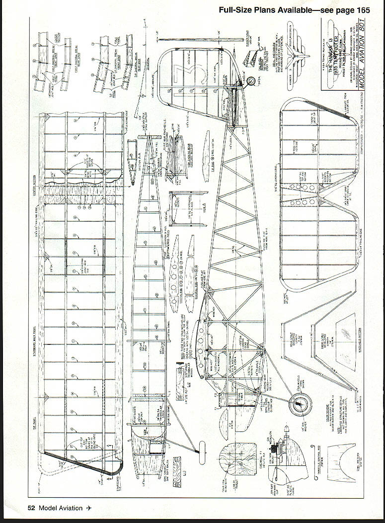
Full-Size Plans Available — see page 165
ACKNOWLEDGEMENT
Credit Jean, my wife of 49 years, for her patience and understanding during this long, drawn-out project; Conrad Hansen, for his original design of the Hangar 13 Ten-Footer; Elwin Lindsley, for his vast knowledge of the writing, publishing, and photographic arts, and for having passed some of that knowledge on to me; Ralph Beck, for building a full-size RC Hangar 13 in 1987, which renewed my interest and rekindled my inspiration.
Thanks also to Jim Alaback, Richard Brown, Hal deBolt, Larry Fair, Bill and Phyllis Hanmer, D.B. Mathews, Jim Noonan, and Bob Oslan. My apologies to anyone who may have been overlooked.
Transcribed from original scans by AI. Minor OCR errors may remain.

