
The Hare
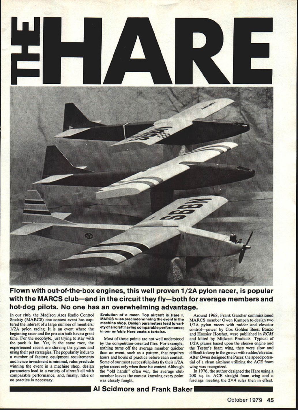
In the Madison Area Radio Control Society (MARCS), one contest event has captured the interest of a large number of members: 1/2A pylon racing. It is an event where the beginning racer and the pro can both have a great time. For the neophyte, just trying to stay with the pack is fun. Yet, in the same race, the experienced racers are shaving the pylons and using their pet strategies. The popularity is due to a number of factors: equipment requirements and hence investment are minimal; rules preclude winning the event in a machine shop; design parameters lead to a variety of aircraft having comparable performance; and little or no practice is necessary.
Most of these points are not well understood by the competition-oriented flier. Nothing turns off the average member quicker than an event, such as a pattern contest, that requires hours and hours of practice before each contest. Some of our most successful pilots fly their 1/2A pylon racers only when there is a contest. Although the "old hands" often win, the average club member leaves the contest knowing every point was closely fought.
Evolution
Around 1968, Frank Garcher commissioned MARCS member Owen Kampen to design two 1/2A pylon racers with rudder and elevator control, powered by Cox Golden Bees. Bonzo and Hoosier Hotshot were published in RCM and kitted by Midwest Products. Typical of 1/2A planes based upon the chosen engine and the Testor's foam wing, they were slow and difficult to keep in the groove with rudder/elevator control.
After Owen designed the Pacer, the speed potential of a clean airplane utilizing the ACE foam wing was recognized. In 1976 the author designed the Hare using a 200 sq. in. ACE straight foam wing and a fuselage meeting the 2x4 rules then in effect. When the ACE GLH appeared in 1977, a new level of performance had been established. Both Frank Baker and the author created versions of a swept-wing Hare with built-up wings. Both were competitive with the GLH and possessed better aerodynamic properties.
At the end of the 1978 season, several local modelers indicated interest in building a Hare for the 1979 season. Frank (who never built two airplanes exactly alike) and the author pooled their variations to provide plans for Hare-V, the version shown on the plans. This version has all the desirable properties of a 1/2A pylon racer: stability (especially at launch); tight cornering without loss of speed or altitude; very fast on the straightaway with superior grooving capability; unusually good wind penetration and ability to plow through turbulence; and a very smooth, controllable glide.
Philosophy and weight
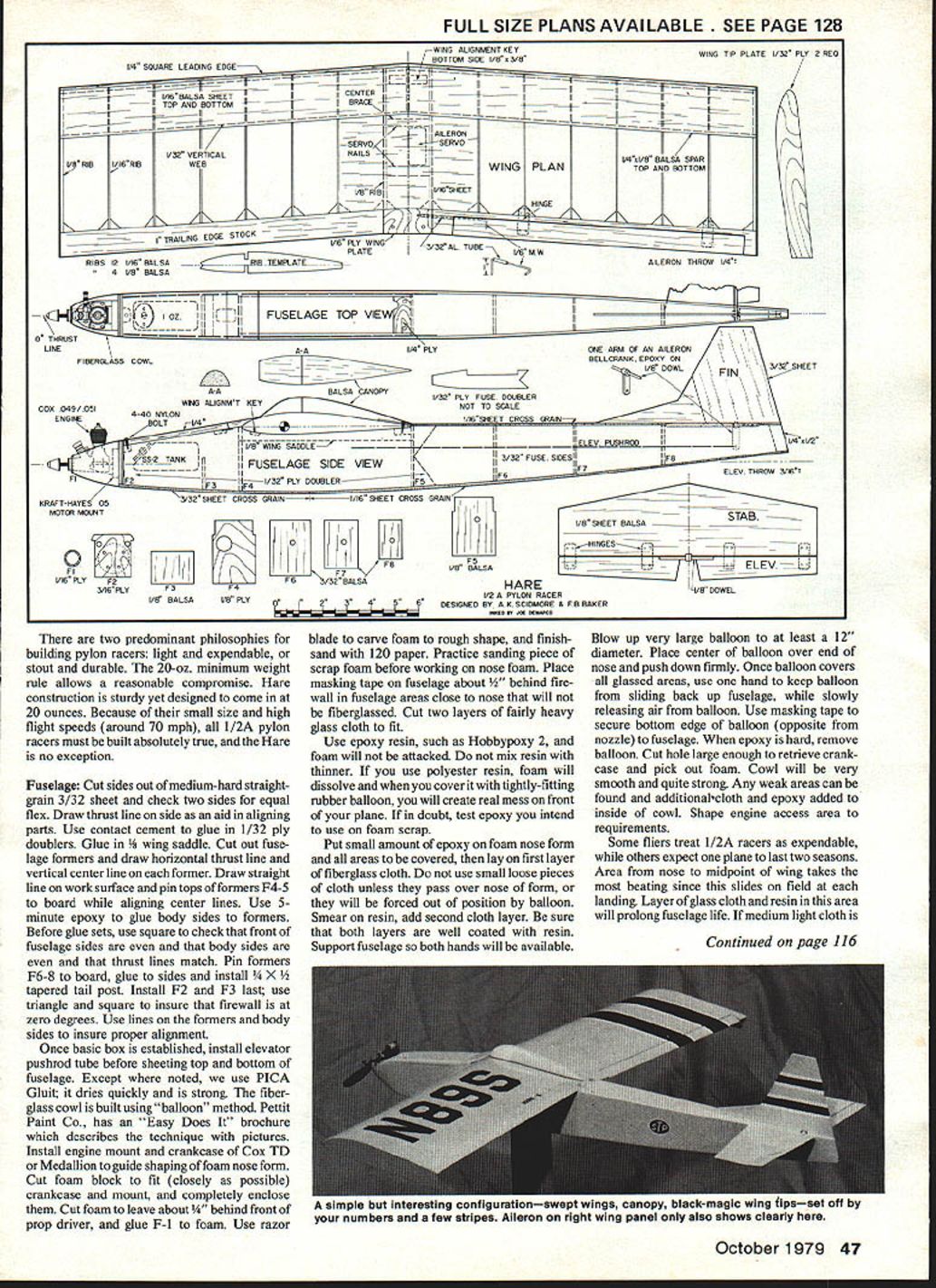
There are two predominant philosophies for building pylon racers: light and expendable, or stout and durable. The 20-oz. minimum weight rule allows a reasonable compromise. Hare construction is sturdy yet designed to come in at about 20 ounces. Because of their small size and high flight speeds (around 70 mph), all 1/2A pylon racers must be built absolutely true, and the Hare is no exception.
Fuselage
- Cut sides from medium-hard straight-grain 3/32" sheet and check two sides for equal flex.
- Draw the thrust line on one side as an aid in aligning parts.
- Use contact cement to glue in 1/32" ply doublers. Glue in F3 and the wing saddle.
- Cut out fuselage formers and draw the horizontal thrust line and vertical center line on each former.
- Draw a straight line on the work surface and pin the tops of formers F4 and F5 to the board while aligning center lines.
- Use 5-minute epoxy to glue body sides to formers. Before the glue sets, use scrap to check that the fronts of the fuselage sides are even, that both sides are even, and that thrust lines match.
- Pin formers F6–F8 to the board, glue to sides, and install a 1/4" x 1/2" tapered tail post.
- Install F2 and F3 last; use a triangle and square to ensure the firewall is at zero degrees. Use the lines on the formers and body sides to ensure proper alignment.
Once the basic box is established, install the elevator pushrod tube before sheeting the top and bottom of the fuselage. Except where noted, PICA Glu-it is recommended; it dries quickly and is strong.
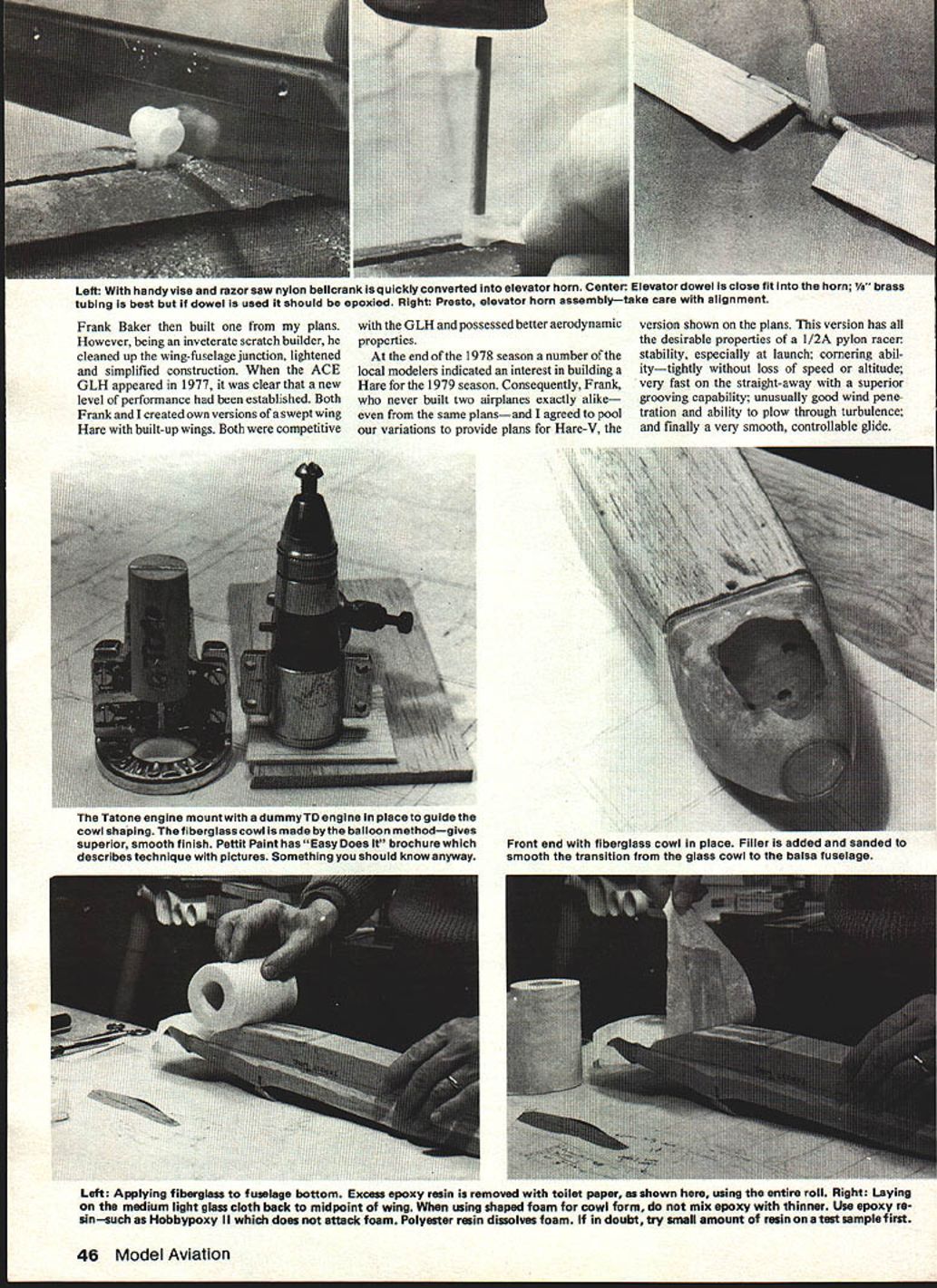
Fiberglass cowl (balloon method)
The fiberglass cowl is built using the "balloon" method (Pettit Paint Co. "Easy Does It" brochure describes the technique).
- Install engine mount and crankcase of Cox TD or Medallion to guide shaping of the foam nose form.
- Cut a foam block to fit the crankcase and mount closely if possible, and completely enclose them. Leave about 1/8" behind the front of the prop driver, and glue F1 to the foam.
- Use a razor blade to carve the foam to rough shape and finish sand with 120 grit. Practice sanding a scrap foam piece before working on the nose form.
- Place masking tape on the fuselage about 1/2" behind the firewall in fuselage areas close to the nose that will not be fiberglassed. Cut two layers of fairly heavy glass cloth to fit.
- Use epoxy resin (such as Hobbypoxy 2); epoxy will not attack the foam. Do not mix resin with thinner. Polyester resin will dissolve foam and must not be used directly on foam — if in doubt, test on a scrap.
- Put a small amount of epoxy on the foam nose form and all areas to be covered, then lay on the first layer of fiberglass cloth. Avoid small loose pieces of cloth that do not pass over the nose of the form.
- Smear on resin and add the second cloth layer. Ensure both layers are well coated. Support the fuselage so both hands are available.
- Blow up a very large balloon to at least 12" diameter. Place the center of the balloon over the end of the nose and push down firmly. Once the balloon covers all glassed areas, hold it in place while slowly releasing air. Use masking tape to secure the bottom edge of the balloon (opposite the nozzle) to the fuselage.
- When the epoxy is hard, remove the balloon. Cut a hole large enough to retrieve the crankcase and pick out the foam. The cowl will be smooth and strong. Add additional cloth and epoxy inside the cowl to reinforce any weak areas. Shape the engine access area as required.
Reinforcement
Some fliers treat 1/2A racers as expendable, while others expect one plane to last two seasons. The area from the nose to the midpoint of the wing takes the most beating since it slides on the field at each landing. A layer of glass cloth and resin in this area will prolong fuselage life. If medium-light cloth is used and excess resin is soaked up with toilet tissue, a very lightweight job can be done.
Wings
Wings are standard; plans call for 1" trailing-edge stock on both panels. Ailerons are cut out later.
- Install aileron servo mounting rails before sheeting the center section. Alignment is crucial.
- An easy way to get true wings is to pin the trailing edge to a truly flat work surface. Place a 1/8" spacer under the trailing edge to elevate it so spars may be pinned flat.
- Glue both top and bottom wing spars in place. While the glue is wet, glue ribs to the trailing edge.
- Use a ruler to ensure the leading edges of all ribs are the same height above the work surface. Glue in the leading edge and hold in place with pins or weights until the glue sets.
- Leave the wing on the board until shear webs are glued in place and the top sheeting is installed. This ensures a straight, true, very strong, rigid, lightweight wing.
- Epoxy-glass the center to strengthen the wing where it meets the fuselage.
- Balance the wing on the center line to check for equal panel weight; adjust by sanding until balanced.
- Install the wing alignment key and tip plates after the basic wing is covered.
Foam wings have been used; the only noticeable difference is they tend to be heavier than built-up wings.
Wing fit and final assembly
- Trim the fuselage wing saddle until the wing fits perfectly horizontal when the fuselage sides are vertical.
- Ensure the wing center line is parallel to the thrust line (zero degrees incidence).
- Install a 1/4" ply wing hold-down block.
- Before drilling pilot holes for wing hold-down screws, use a string to measure that the tip of each wing is the same distance from the fuselage.
- From the front, carve the front hold-down block from balsa to fit the wing and glue in place.
- Install the elevator; be sure it is horizontal relative to the wing. Use a triangle to check that the fin is vertical. Sight the fin from the front to ensure it is true and parallel to the fuselage center line.
Covering and finishing
Various covering schemes have been used. Heat-shrink coverings (Solar Film, Econokote, etc.) work well. One builder uses film without painting and covers all surfaces; another films the fuselage back to the leading edge and paints forward of that. Use colors and trim that make the plane highly visible and easily distinguishable from other aircraft. Whites, yellows, and orange combinations work well.
Flying
Your Hare should be set up so it grooves yet turns rapidly. Aileron and elevator throws shown on the plans are approximate. Roll rate should be positive without being too quick. Too much aileron or elevator throw can make any aircraft difficult to handle.
- Initiate a turn with elevator, then use aileron to tighten the turn. Allow the nose to drop slightly during a turn.
- Adjust the center of gravity until straight-and-level flight can be maintained with no elevator input.
If you built a true airplane that weighs between 20 and 21 ounces, the properties described above should be achieved. The only other prerequisite is the hottest possible out-of-the-box engine. Any 1/2A pylon racer is no better than its engine and pilot.
Plans
Full-size plans available — see page 128.
Transcribed from original scans by AI. Minor OCR errors may remain.

