
Hawker Hunter
A very successful British fighter of the 1950s, the Hawker Hunter served admirably with the RAF and other nations, including Denmark, Holland, Peru, Sweden, and Switzerland. Powered by a Rolls-Royce Avon turbojet developing 10,000 lb of thrust, the full-size aircraft cruises at about 700 mph at low level and has a service ceiling near 53,000 ft.
The Hunter is a good-looking airplane owing to fine engineering and clean lines. Full-size dimensions:
- Wingspan: 33 ft 8 in
- Length: 45 ft 10 in
- Gross weight: 24,600 lb
Leading-edge extensions provide extra stability and contribute to the design's excellent flying qualities.
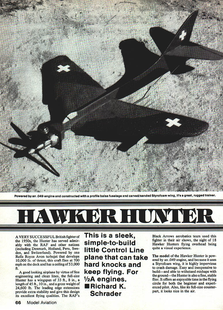
This is a sleek, simple-to-build control-line scale model that can take hard knocks and keep flying. Designed for 1/2A (.049) engines, it is easy and inexpensive to build and highly crash-resistant thanks to a Styrofoam wing. It is a fine, stable flier suitable for both beginners and experienced pilots, and—like its full-size counterpart—looks attractive in the air.
Note: The Black Arrows aerobatics team used the Hunter in their air shows; the sight of 18 Hawker Hunters flying overhead is a striking visual experience.
— Richard K. Schrader
Construction
Wing
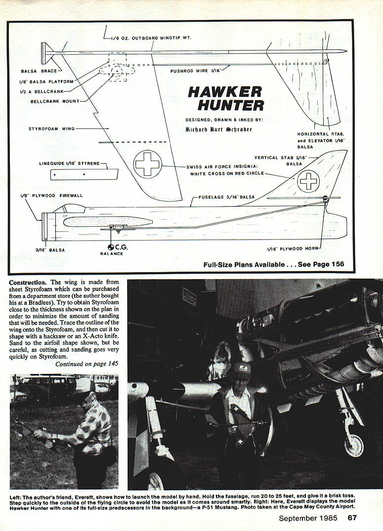
The wing is cut from sheet Styrofoam, which can be purchased from a department store (the author bought his at Bradlees). Try to obtain Styrofoam close to the thickness shown on the plan to minimize sanding. Trace the outline of the wing onto the Styrofoam and cut it to shape with a hacksaw or an X-Acto knife. Sand to the airfoil shape shown on the plan, but be careful: cutting and sanding Styrofoam goes very quickly.
Add 1/8 oz of weight to the outboard wing tip; this helps prevent the model from rolling toward the inside of the flying circle.
Fuselage and tail
- Cut the fuselage from 3/16 in sheet balsa and cut out the section where the wing will go.
- Cut the vertical stabilizer from 3/16 in sheet balsa and glue it to the fuselage.
- Make the firewall from 1/8 in plywood; epoxy the bellcrank in place with 3/16 in balsa support braces.
- Cut the horizontal stabilizer and elevator from 1/16 in sheet balsa. Cut the slot in the vertical stabilizer and glue the horizontal stabilizer in place.
- Attach the elevator to the stabilizer with cloth hinges (or any preferred hinge method). Glue a 1/16 in plywood horn onto the elevator.
- Sand the edges of the fuselage, vertical stabilizer, horizontal stabilizer, and elevator.
Installation
- Install the wing and glue it with liberal amounts of epoxy.
- Cut a notch in the Styrofoam for the 1/8 in sheet balsa platform and epoxy this and the plywood bellcrank mount in place.
- Glue on the line guide, which can be made of 1/16 in balsa or styrene plastic.
- Epoxy the bellcrank and mounts as required.
- Mount the engine with wood screws.
- Install the pushrod, bend the wire to fit, and adjust so the elevator has equal up and down travel.
Finishing
Brush a coat of clear dope onto the fuselage and balsa tail surfaces only—do not allow the dope to touch the Styrofoam. Let the clear dope dry for 24 hours before applying color.
The model shown was finished in Swiss Air Force colors: gray undersides with dark green and dark gray on top. If possible, spray the color for a thinner, lighter coat; brushing is acceptable. The author used Aerogloss polyurethane paint: two coats on the fuselage and one on the wing.
Mask the cockpit area and paint it light blue. The Swiss Air Force insignia (white crosses on red circles) was cut from MonoKote trim sheets.
When finishing is complete, install the bellcrank, fit and bend the pushrod for proper travel, and mount the engine.
Balance point (CG)
- The balance point shown on the plan indicates, with a full fuel tank, the most forward limit of the center-of-gravity (CG) range.
- The most rearward limit is the bellcrank mounting screw.
- Within this range, balance forward for maximum stability and rearward for maximum maneuverability.
- To check balance: hold the fuselage between two fingers at the balance point. When correctly balanced, the model will sit level.
Flying
- Use 26 ft control lines. Check the AMA rule book (pages 17–18) for recommended line-ending methods.
- Ensure the elevator moves freely with minimum line tension. Do not fly near overhead power lines.
Takeoff (with a helper)
- Have your helper hold the model by the fuselage.
- Run 20 to 25 feet while holding the model, and launch it into the air in a level attitude.
Landing
- Anticipate when the fuel is about to run out.
- Fly the model level at about shoulder height.
- When the engine quits, let the model glide to a landing, applying up-elevator just prior to touchdown.
Crash repairs
- The Styrofoam wing is highly resistant to crash damage. Minor mishaps usually require little or no repair.
- For a bad crash that breaks the wing, a field repair with 5-minute epoxy will often restore the wing almost invisibly.
Personal note
A word about my friend Everett, shown in the pictures: he is one of the kindest, most caring people I have met. He has an intellectual disability, but that does not interfere with his genuine interest in aviation or his willingness to help out. His example is one from which we can all learn and benefit.
Transcribed from original scans by AI. Minor OCR errors may remain.

