

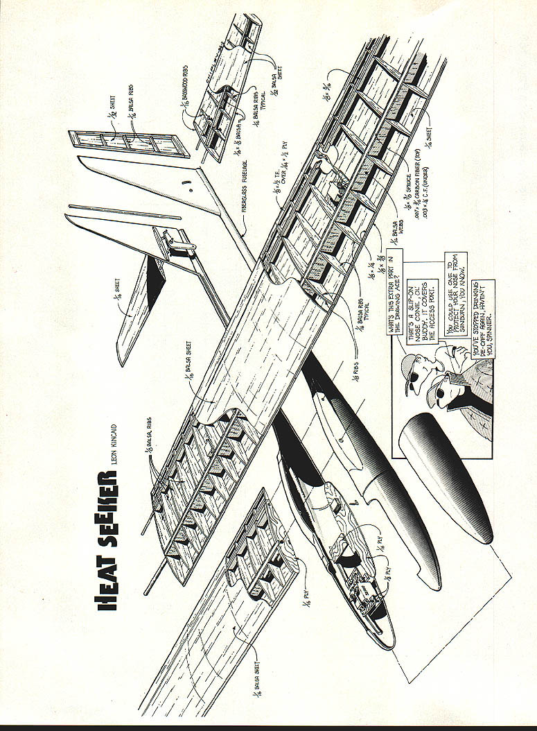
Heat Seeker
Leon Kincaid
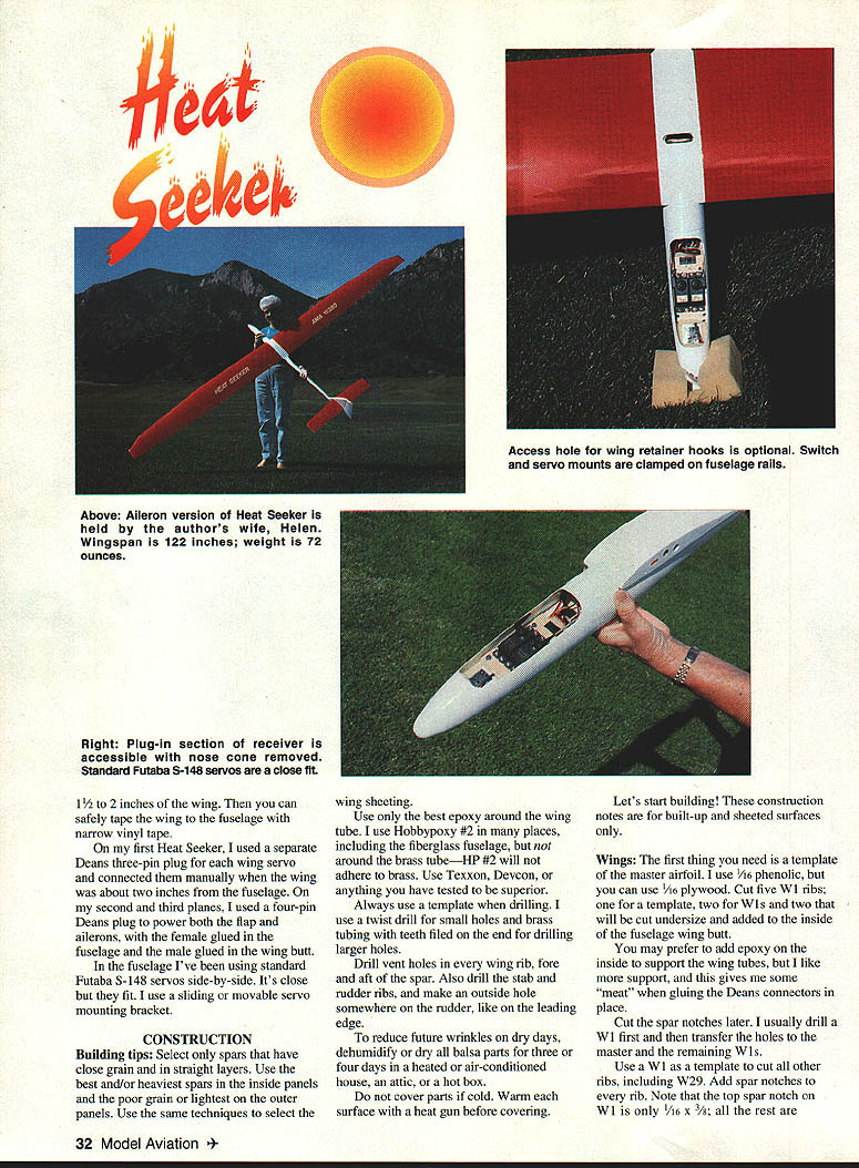
Heat Seeker is a sailplane for everyone. It can be built as an aileron airplane or rudder-controlled with polyhedral. It can be 114 or 122 inches in wingspan, and all versions are sheeted over built-up wings and stab (or sheeted over foam).
I wanted a modern-looking design without going whole-hog high-tech or spending $400–800 on a new sailplane. Many modelers still prefer traditional construction methods, so I designed the Heat Seeker around my standard planform and cleaned it up where possible. I reduced my Scooter’s airfoil thickness from 12% to 11% while maintaining the same mean camber (MC) of about 3.3% — roughly halfway between the S3021 and SD7032. My airfoils have placed first at the AMA Nats five times, so they can’t be too bad. The Heat Seeker placed first in SMT at the 1992 and 1993 LSF Championships, flown by John Gunsaullus.
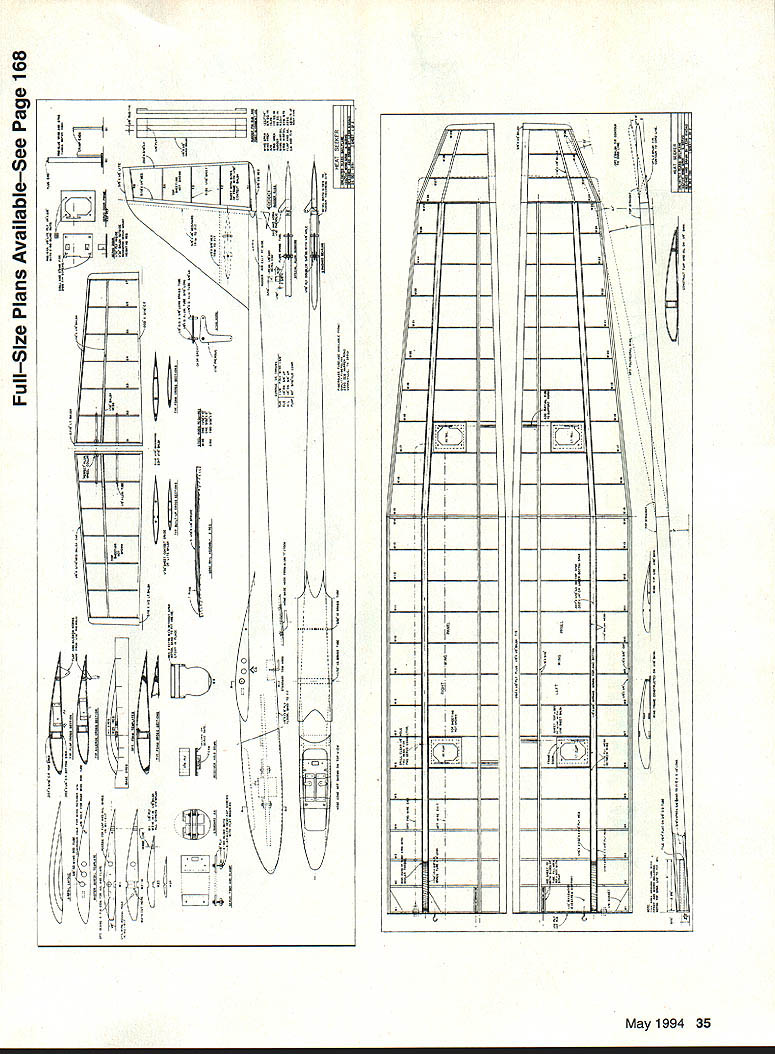
The plans show basic built-up wing and tail surfaces, completely sheeted, and also include templates for cutting foam cores if you prefer that method.
The first thing most people notice is the light stab. If you’ve flown free flight or hand-launched gliders, or seen HLG drawings, you’ll notice the small, skinny fuselage. These gliders tolerate rough landings because the stabs and rudder are built very thin and light, which reduces stress on the fuselage. Do not use solid sheet to save time — keep stabs and rudder as light as possible. The spars in the stab are primarily to keep ribs from falling over, and the webs give a place to hold the stab during installation and removal.
I use eight-inch-wide 1/16" wing sheeting from Superior Aircraft. Foam templates shown are sized for 1/16" sheeting; if you use thinner obeche sheeting you will need to modify the templates. If you have Chuck Anderson’s airfoil program, select the Scooter 33 airfoil, reduce it to 11%, and plot any skin thickness you desire.
A number of small details are not shown on the drawings because everyone has their own methods. For example, I cut a small slot in the top of my fuselage to access wing screw-eye retainer hooks; others tape the wings to the fuselage. If you film-cover a wing, the film can pull away from the sheeting; wrap clear 3M tape around the last 1½–2 inches of the wing, then tape the wing to the fuselage with narrow vinyl tape.
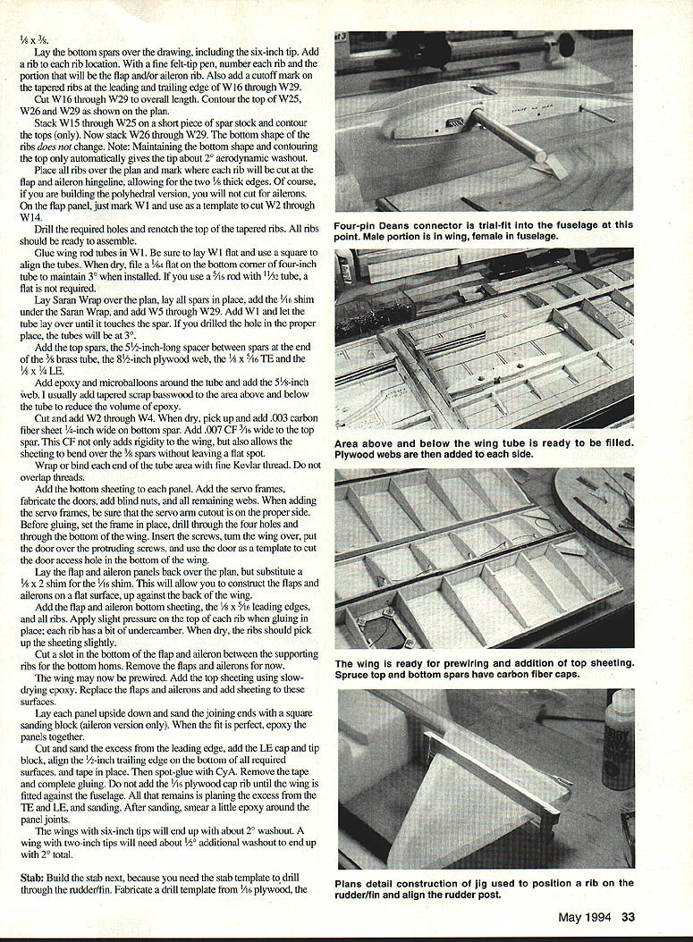
On my first Heat Seeker I used a separate Deans three-pin plug for each wing servo, connecting them manually when the wing was about two inches from the fuselage. On later ships I used a four-pin Deans plug to power both flap and aileron servos, with the female glued in the fuselage and the male glued to the wing butt. I use standard Futaba S-148 servos side-by-side in the fuselage; it’s a close fit so I use a sliding or movable servo mounting bracket.
Specifications
- Type: RC sailplane
- Wingspan: 114 or 122 inches
- Number of servos: Six (typical)
- Flying weight: ~72 ounces (each of my three Heat Seekers weighed 72 oz)
- Construction: Fiberglass fuselage, sheeted surfaces (built-up or foam)
- Covering/finish: Hobbypoxy on fuselage finishes; MonoKote on flying surfaces
CONSTRUCTION
Building tips
- Select spars with close, straight grain. Use the best/heaviest spars in the inside panels and the poorest-grained/lightest spars on the outer panels. Use the same selection technique for wing sheeting.
- Use high-quality epoxy around the wing tube. I use Hobbypoxy #2 in many places (but not directly on brass — test adhesives you plan to use). Devcon or any epoxy you've proven reliable is acceptable.
- Always use a template when drilling. Start with small pilot holes and use a twist drill; for larger holes use brass tubing with teeth filed on the end for cutting.
- Drill vent holes in every wing rib, fore and aft of the spar. Also drill stab and rudder ribs and add an outside hole somewhere on the rudder near the leading edge.
- To reduce wrinkles on dry days, dry all balsa parts for three to four days in a heated, air-conditioned house, attic, or hot box. Do not cover parts if cold; warm each surface with a heat gun before covering.
Construction notes that follow apply to built-up and sheeted surfaces only.
Wings
- Make a master airfoil template. I use 1/16" phenolic (1/8" plywood will work). Cut five W1 ribs: one template, two for W1s, and two undersize ribs to add inside the fuselage wing butt.
- You may epoxy inside the wing butt for added support where the wing tubes and Deans connectors glue in. This gives some "meat" for gluing connectors.
- Cut spar notches later. I usually drill W1 first and transfer the holes to the master and the remaining W1s. Use W1 as a template to cut all other ribs, including W29. Add spar notches to every rib. Note: the top spar notch on W1 is only 1/16" × 3/8"; the rest are 1/8" × 3/8".
- Lay the bottom spars over the drawing, including the six-inch tip. Add a rib at each rib location. Number each rib and mark flap/aileron ribs; add cutoff marks on tapered ribs at the leading and trailing edges from W16 through W29. Cut W16–W29 to overall length and contour the top of W25, W26 and W29 as shown on the plan. Stacking and contouring the tops of ribs (while keeping the bottom shape) automatically gives the tip about 2° aerodynamic washout.
- Mark hinge lines for flaps and ailerons, allowing for two 1/8" thick edges. If building the polyhedral version, do not cut for ailerons. On the flap panel mark W1 and use it as a template for W2–W14. Drill required holes and re-notch the top of tapered ribs. All ribs should then be ready to assemble.
- Glue wing rod tubes into W1. Lay W1 flat and square the tubes. When dry, file a 1/64" flat on the bottom corner of a 4" tube to maintain 3° when installed (not required if using 5/16" rod with 1½" tube).
- Lay Saran Wrap over the plan, lay all spars in place, add a 1/16" shim under the Saran Wrap, and add W5–W29. Add W1 and allow the tube to lay over until it touches the spar — if drilled properly, the tubes will sit at 3°.
- Add top spars, a 5½" spacer between spars at the end of the 3/8" brass tube, the 8½" plywood web, the 1/4" × 1/16" TE, and the 1/8" × 1/4" LE. Apply epoxy and microballoons around the tube and add the 5/16" web. I often add tapered scrap basswood around the tube area to reduce epoxy volume.
- Cut and add W2–W4. When dry, add carbon fiber reinforcement: .003" CF sheet 3/4" wide on the bottom spar and .007" CF 3/16" wide to the top spar. This adds rigidity and helps the sheeting bend over 3/8" spars without flat spots.
- Wrap or bind each end of the tube area with fine Kevlar thread (do not overlap threads).
- Add bottom sheeting to each panel, install servo frames, fabricate doors, add blind nuts and remaining webs. When adding servo frames, check servo arm orientation. To make the door access hole: set the frame, drill through four holes and the bottom of the wing, insert screws, turn the wing over, put the door over the protruding screws, and use the door as a template to cut the access hole in the bottom.
- Lay flap and aileron panels back over the plan using a 1/8" × 2" shim instead of 1/16" — this builds flaps and ailerons flat. Add bottom sheeting, 1/8" × 5/16" leading edges, and all ribs. Apply slight pressure to the top of each rib during gluing so the undercamber is picked up by the sheeting when dry. Cut a slot in the bottom of the flap and aileron between supporting ribs for the bottom horns. Remove flaps and ailerons for the moment.
- Pre-wire the wing if desired. Add top sheeting with slow epoxy, replace flaps/ailerons and sheet them. Lay each panel upside down and square-sand the joining ends (aileron version only). When the fit is perfect, epoxy the panels together.
- Cut and sand excess from the LE and TE, add the LE cap and tip block, align a 1/2" TE on the bottom of required surfaces and tape in place, spot-glue with CyA, remove the tape and complete gluing. Do not add the 1/8" plywood cap rib until the wing is fitted to the fuselage. After sanding, smear some epoxy around panel joints.
- Wings with six-inch tips will end up with about 2° washout. A wing with two-inch tips will need about 1/2° additional washout to end up with 2° total.
Stab
- Build the stab next because you need the stab template to drill through the rudder/fin. Make a drill template from 1/16" plywood the same length and width as S1; leave it rectangular. Drill two 1/2" holes for the stab tubes 1½" apart and 1-7/8" from the LE.
- Use the template to cut and drill four 1/16" basswood ribs for S1 and S2, and ten 1/16" balsa ribs. Number S1 through S7 and contour S1 and S7 as shown on the plan.
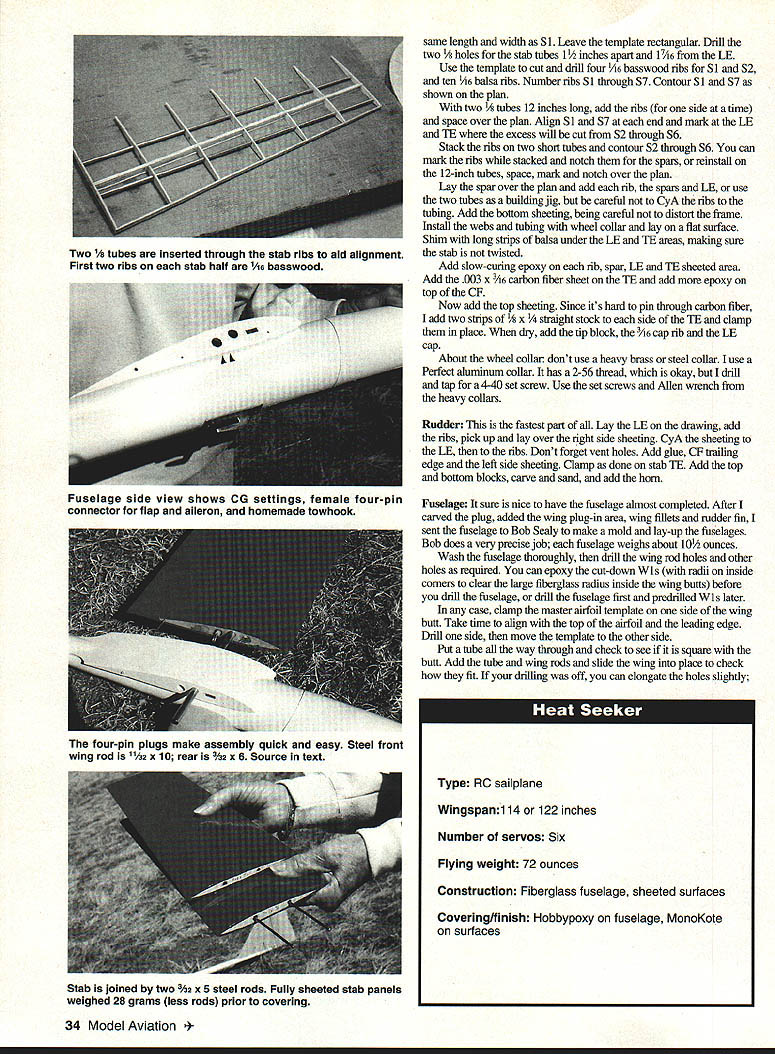
- With two 1/8" tubes 12" long as a jig, add ribs for one side at a time and space over the plan. Align S1 and S7 and mark where excess will be cut from S2–S6. Stack ribs on short tubes and contour S2–S6. Mark and notch ribs for spars while stacked or reinstall on the 12" tubes and finish notching over the plan.
- Lay the spar over the plan and add each rib and the LE, or use the tubes as a building jig (do not CyA ribs to the tubing). Add bottom sheeting carefully to avoid distortion. Install webs and tubing with wheel collar and lay on a flat surface. Shim under the LE and TE with long strips of balsa to ensure the stab is not twisted.
- Add slow-curing epoxy on each rib, spar, LE and TE sheeted area. Add .003" × 3/16" carbon fiber sheet on the TE and more epoxy on top of the CF. Add top sheeting. Because it’s hard to pin through carbon fiber, add two strips of 1/8" × 1/4" straight stock to each side of the TE and clamp them in place while drying. When dry, add the tip block, 3/16" cap rib and LE cap.
- Use a light aluminum wheel collar (not heavy brass/steel). I use a Perfect aluminum collar, drill and tap for a 4-40 set screw, and use the set screws and Allen wrench from heavier collars.
Rudder
- The rudder is quick to build. Lay the LE on the drawing, add ribs, pick up and lay over the right-side sheeting. CyA the sheeting to the LE and ribs (don’t forget vent holes). Add CF trailing edge, left-side sheeting, clamp as done on the stab TE, add top/bottom blocks, carve, sand and add the horn.
Fuselage
- After carving the plug and adding the wing plug-in area, wing fillets and rudder fin, I sent the fuselage plug to Bob Sealy to mold and lay up the fuselages. Each fiberglass fuselage weighs about 10½ ounces.
- Wash the fuselage thoroughly, then drill wing rod holes and other required holes. You can epoxy the cut-down W1s (with radii on inside corners to clear the large fiberglass radius inside the wing butts) before drilling the fuselage, or drill the fuselage first and predrilled W1s later.
- Clamp the master airfoil template on one side of the wing butt, aligning it with the top of the airfoil and the leading edge. Drill one side, then move the template to the other side. Insert a tube through and check for squareness with the butt. Add the tube and wing rods and slide the wing into place to check fit. If drilling was slightly off, holes can be elongated slightly to correct alignment.
Finishing
- On the first Heat Seeker I sprayed white automotive primer, filled pinholes with Model Magic, sanded and primed again, then finished with white lacquer (chips easily).
- The second fuselage used the same primer but was finished with white Formula U (harder finish, heavier than lacquer).
- On the third model I used Hobbypoxy undercoat and Hobbypoxy paint with quick spray hardener — a super-hard, light finish.
- Spray white finishes only; darker colors absorb heat and can weaken fiberglass.
- I recommend covering wings, stabs and rudder with MonoKote and using Vinylwrap lettering. I hinge flaps and ailerons with MonoKote tabs. If using tape, tape flaps on the bottom and ailerons on the top of the wing.
Radio and Servos
- I use a Futaba 7UAFS with S-148s in the fuselage. The standard servo from the JR X347 sailplane version fits well.
- For flaps I have used S-9601s and S-302s — both use the same case and metal gears; the S-302 is slower with higher torque. Both are similar in size to the Airtronics 401.
- Ailerons use S-5102s (an S-136 with metal gears); my third plane uses JR 341s in the wings.
- On the plan I show servos held by short blocks glued to the door. Mark, drill and tap these blocks in a vise before gluing to the doors to prevent splitting. If you prefer servo tape, leave the blocks off and smear epoxy on the plywood side of the door, cover with Saran Wrap, lay face down on a slick surface, add weight and let dry. Peel off the wrap for a super-slick surface for the tape.
Balancing
- Assemble the plane and balance at the most aft CG you plan to use.
- Tape a small paper cup on top of the nose and pour in lead shot until the plane balances.
- Remove the nose cone and battery, sit or hang the fuselage vertical, and pour the lead shot into the nose. Mix about a tablespoon of epoxy and pour on top of the shot. When cured, add a round disk of foam and reinstall the battery.
Flying and First-Flight Procedure
- Heat Seeker flies much like a fast Scooter; how it flies depends mainly on the pilot and setup. The throws on the plans will get an average novice safely in the air. Final correlation between rudder/aileron and flaps/elevator depends on your radio and trimming technique.
- To avoid breaking a new plane during initial test flights, use this safe first-flight procedure:
- Balance on the CG mark shown on the drawing and put the tow hook directly under the CG.
- Place the fuselage on a table or workbench (wings can be removed).
- Shim the fuselage until the top of the tailboom is level with the table; the wing incidence will be about 1.4–1.5° positive in this position.
- With the radio on, set the stabs to 0°. Measure the same distance from the table to the center of the stab leading edge and to the stab trailing edge.
- Put a small mark on the rudder/fin at the stab leading edge with a felt-tip pen. With this CG, wing angle, stab setting and tow hook position, the first launch should be very predictable and the glide level. You can comfortably grab the fuselage under the wing for launching.
Good luck and have fun!
Sources
- Fiberglass fuselage and foam cores: Bob Sealy, Cookeville, TN 38501; Tel.: (615) 526-4770.
- Thin carbon fiber and Kevlar thread: Bradley Model Products, 1337 Pine Sap Ct., Orlando, FL 32825; Tel.: (407) 277-9132.
- Eight-inch-wide balsa sheeting: Superior Aircraft Materials, Hawaiian Gardens, CA 90716; Tel.: (800) 488-9525.
- The best 1/32 wing rods: Dave Squires, 935B La Mesa Terrace, Sunnyvale, CA 94086; Tel.: (408) 245-8111.
Transcribed from original scans by AI. Minor OCR errors may remain.

