
Heinkel 100
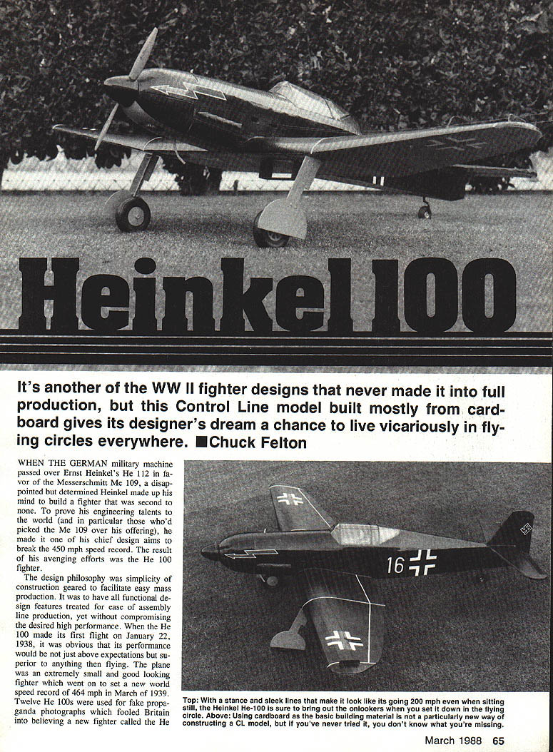
It's another WWII fighter design that never made full production. This control-line model, built mostly of corrugated cardboard, gives its designer's dream a chance to live vicariously — flying circles everywhere. By Chuck Felton.
When the German military machine passed over Ernst Heinkel's He 112 in favor of the Messerschmitt Me 109, Heinkel, disappointed but determined, set out to build a fighter second to none. His chief design aim was to break the 450 mph speed record. The result was the He 100. The design philosophy emphasized simplicity of construction to facilitate easy mass production: all functional features were treated for assembly-line ease without compromising high performance. The He 100 first flew on January 22, 1938, and in March 1939 set a world speed record of 464 mph.
Heinkel never sold the He 100 to the Luftwaffe, which had already based its fighter program on the Me 109 and Me 110 and preferred overwhelming the enemy by numbers. After the war, both Russia and Japan purchased three He 100 aircraft apiece for design study. One can see the He 100's influence on the Russian Yak-3 and Yak-9 and the Japanese Kawasaki Ki-61 ("Tony").
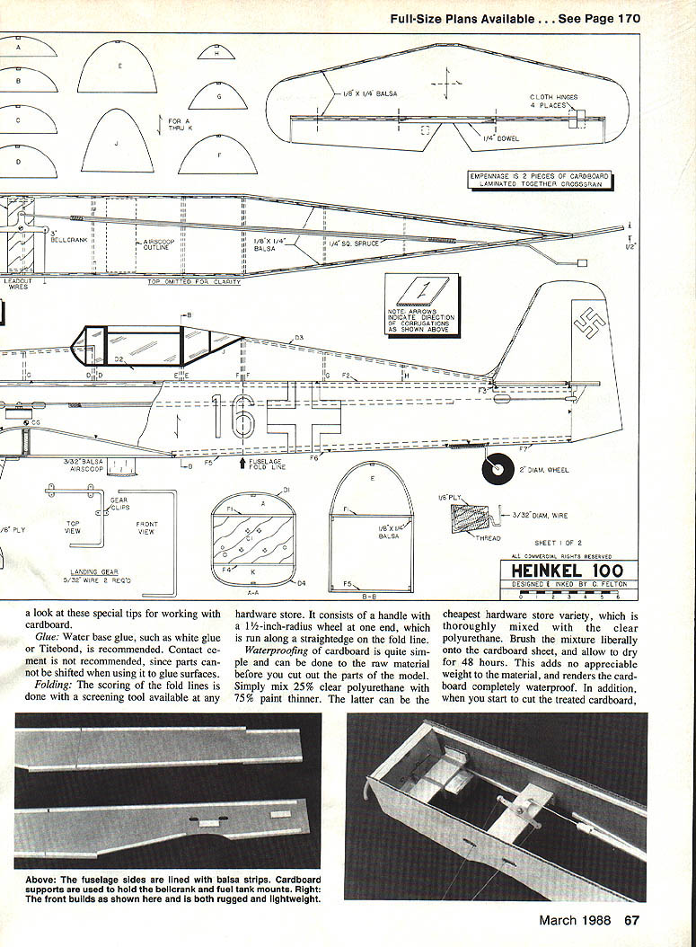
Full-size plans available: page 170.
Model overview
- Scale: 2 inches to the foot.
- Wingspan: 61 in.
- Length: 53 in.
- Airfoil: flat bottom; curved upper surface obtained by scoring/folding.
- Recommended engine: .30–.40 size range.
- Construction materials: primarily corrugated cardboard with balsa/spruce spars and minimal internal bracing.
- Characteristics: low cost, lightweight, fast to build, good scale appearance, robust for sport flying.
Materials and tools
- Corrugated cardboard (1/8-in. corrugated recommended; heavier grades may be used where noted).
- Balsa: various strips (1/8 x 1/4 in., 3/8 x 1/4 in., etc.).
- Spruce: 1/4 x 1/4-in. spar caps.
- Plywood: 1/8-in. and 1/4-in. ply for joiners, gear mounts, firewall, wheel pants.
- Dowels: 1/4-in. and 3/16-in. as specified.
- Music wire: 3/32-in. for main and tail gear.
- Blind nuts, washers, nylon gear clips.
- Glue: water-based white glue or Titebond recommended. Avoid contact cement.
- Gummed paper tape: 1-in. wide roll (stationery store).
- Screening tool for scoring (handle with ~1-1/2-in. radius wheel).
- Clear polyurethane and paint thinner (for waterproofing).
- Sandpaper: #400 and others for finishing.
- Covering options: Solarfilm, MonoKote, vinyl paper (dope not recommended under these).
Construction hints and special tips
- Cardboard selection: look for cardboard with white-finished paper on one side; use the white side out for a smoother finish. Sources: box manufacturers, shopping centers (discarded boxes).
- Waterproofing (optional): mix 25% clear polyurethane with 75% paint thinner; brush liberally on cardboard sheets and allow to dry 48 hours. This adds little weight and improves cut edges.
- Folding/score technique: score fold lines using the screening tool run along a straightedge; this produces a crisp fold and a curved upper surface when folded.
- Paper tape: dip thin strips of gummed paper tape in water and smooth over seams, joints, and exposed corrugations to seal and strengthen edges.
- Glue: use water-base glue to allow position adjustments during assembly.
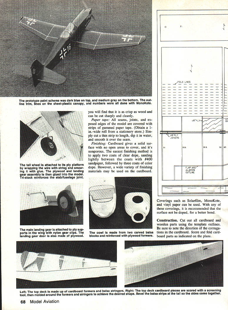
- Finishing: cardboard is nonporous. Recommended finish is two coats of clear dope (sand lightly between coats with #400), followed by three coats of color dope. If using iron-on coverings (Solarfilm, MonoKote, vinyl paper), do not apply dope first for better adhesion.
Building the model
General: Cut out all cardboard and wooden parts using template outlines. Note direction of corrugations. Score and fold cardboard parts as indicated on the plans.
Tail surfaces
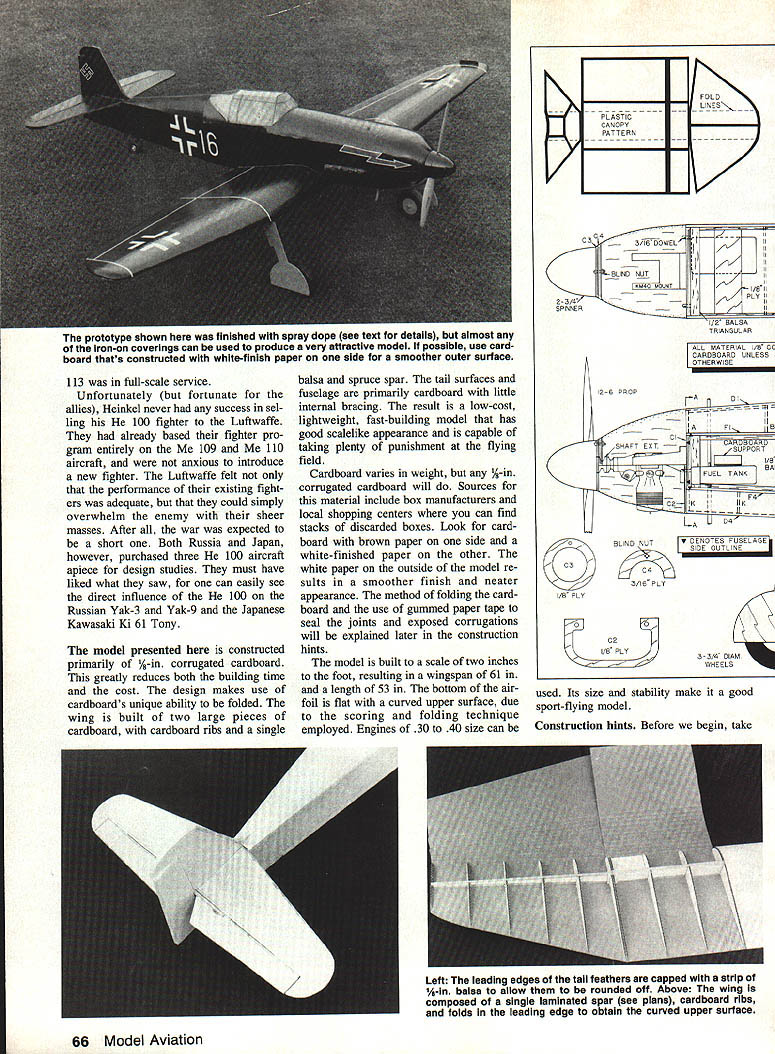
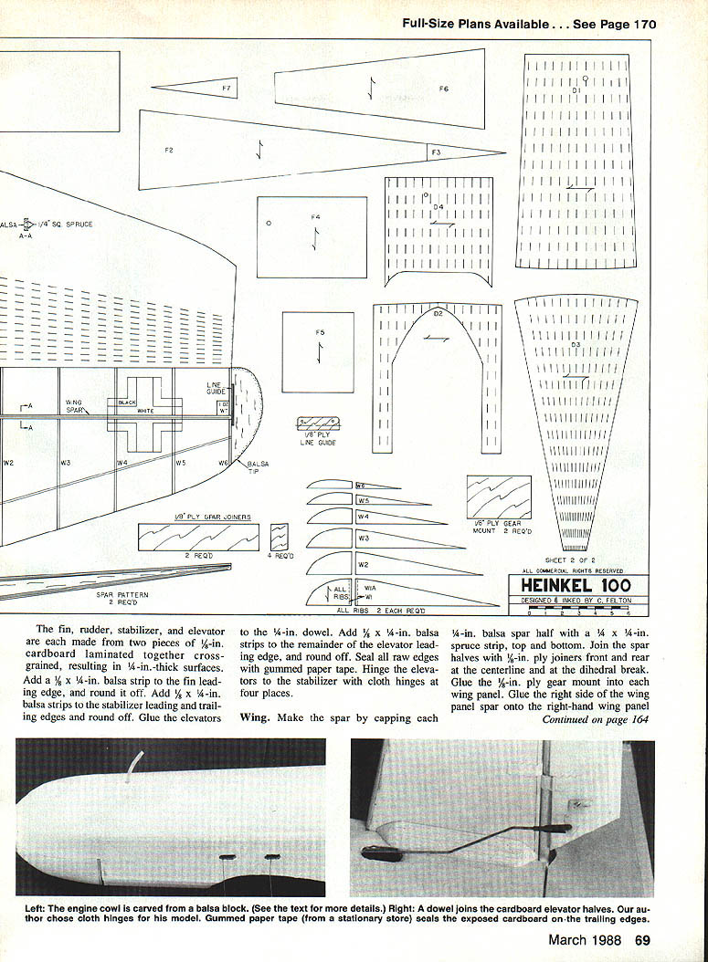
- Make fin, rudder, stabilizer, and elevator from two pieces of 1/8-in. cardboard laminated together cross-grained to produce 1/4-in.-thick surfaces.
- Cap leading edges of tail feathers with 1/8-in. balsa strips to allow rounding.
- Add 1/8 x 1/4-in. balsa strip to the fin leading edge and round off.
- Add 3/8 x 1/4-in. balsa strips to stabilizer leading and trailing edges and round off.
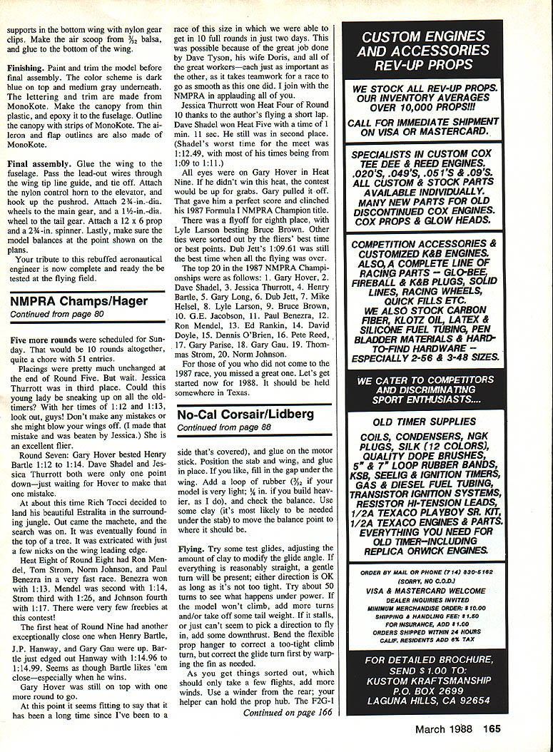
- Glue elevators to a 1/4-in. dowel; add 3/8 x 1/4-in. balsa strips to elevator leading edges and round off.
- Seal raw edges with gummed paper tape.
- Hinge elevators to stabilizer with cloth hinges at four places.
Wing
- Spar: make a laminated spar by capping each 1/8-in. balsa spar half with 1/4 x 1/4-in. spruce strips top and bottom. Join spar halves with 1/8-in. ply joiners front and rear at the centerline and at the dihedral break.
- Glue 1/8-in. ply gear mount into each wing panel.
- Assemble right wing panel: glue right-side wing panel spar onto right-hand wing panel, glue outboard spar portion to bottom wing from W2 through W6, glue cardboard ribs into the right wing, add cardboard doubler over ply gear mount between ribs W1A and W1, glue a 1-oz. weight to the right wing tip for balance.
- Assemble left wing panel similarly and add rib and gear doubler.
- Apply glue to the top of the inboard wing spar (centerline to dihedral break), to the tops of the ribs, and to the trailing edge of the inboard wing; fold the top wing surface down and pin until dry. Repeat for outboard panels.
- Add balsa wing tips.
- Make a line guide from 3/8-in. ply: cut a slot in the left balsa wing tip and glue the line guide in place.
- Cover trailing edge and all seams with gummed paper tape.
Fuselage
- Outline fuselage sides as shown on plans. Line upper and lower edges of each fuselage side with 1/8 x 1/4-in. balsa strips recessed 1/8 in. from the fuselage edge; bevel strips at aft end so sides come together cleanly.
- Add cardboard supports to each fuselage side above the fuel tank area and below the bellcrank.
- Firewall (C1): make from 1/4-in. ply. Locate mounting holes for KM-40 engine mount, drill holes, and install blind nuts on back side. Drill fuel-tubing exit hole and two holes for 3/16-in. dowels; glue dowels into C1. Line all four back edges of C1 with 1/2-in. triangular balsa for bracing.
- Glue C1 to right fuselage side; when dry, glue left fuselage side to C1.
- Attach fuel tank to 5/16-in. ply support (rubber bands acceptable). Make pushrod from 3/32-in. wire with 1/4-in. sq. spruce and attach to bellcrank along with lead-out wires. Install tank and bellcrank assemblies by gluing ply supports to cardboard supports on fuselage sides. Bring fuel fill and overflow lines out during all covering operations.
- Cover fuselage top and bottom: glue F1, F2, F3 in place to cover top of fuselage (ensure fuel tubing exits remain accessible). Cover bottom of fuselage with F4 through F7.
- Add bulkheads A through J to top fuselage. Cover bulkheads A–D with D1 (scored and folded), D–F with D2, F–H with D3. Add three K bulkheads to forward bottom fuselage and cover with D4.
Cowl
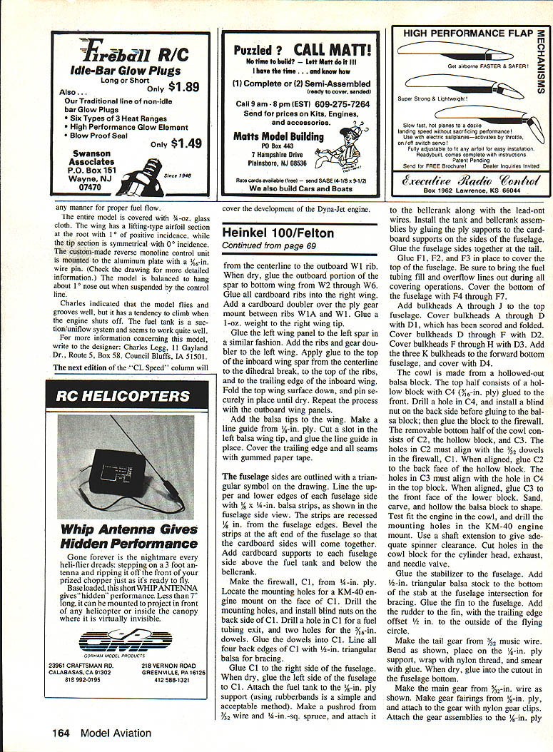
- Make cowl from a hollowed balsa block.
- Top half: hollow block with C4 (3/16-in. ply) glued to front; drill hole in C4 and install blind nut on back before gluing block to firewall. Align dowels in C4/C1.
- Bottom half (removable): consists of C2, hollow block, and C3. Holes in C2 must align with dowels in firewall C1; glue C2 to back face of hollow block. Holes in C3 must align with hole in C4; glue C3 to front face of lower block.
- Sand, carve, and hollow balsa block to shape. Test-fit engine in cowling and drill mounting holes in KM-40 engine mount. Use a shaft spacer for spinner clearance. Cut holes in cowl block for cylinder head, exhaust, and needle valve.
Finishing assembly
- Glue stabilizer to fuselage and add 1/8-in. triangular balsa stock to bottom of stab at fuselage intersection for bracing.
- Glue fin to fuselage and add rudder with trailing edge offset 1/8 in. to the outside of the flying circle (for control-line trim).
- Make tail gear from 3/32-in. music wire: bend as shown on plans, place on 1/4-in. ply support, wrap with nylon and smear glue; when dry glue into cutout in fuselage bottom.
Landing gear and wheels
- Main gear: make from 3/32-in. wire as shown on plans.
- Make gear fairings from 1/8-in. ply and attach to gear with nylon gear clips.
- Attach gear assemblies to 1/8-in. ply blocks with blind nuts; install wheels and secure with washers.
- Glue 1/8-in. ply wheel pants to gear fairings; trim and sand fuselage openings to match wheel pants.
- Drill holes for axle and attach wheels. Fit landing gear into fuselage and align.
- Add 1/4-in. triangular balsa stock to landing gear openings for reinforcement.
Finishing and covering
- Seal all seams, joints, and exposed corrugations with gummed paper tape.
- If doped finish is desired: apply two coats of clear dope, sand lightly between coats with #400 sandpaper, then apply three coats of color dope.
- If using iron-on or heat-shrink coverings (Solarfilm, MonoKote, vinyl paper), do not apply dope first; apply covering directly for better bond.
Notes
- Cardboard reacts differently depending on weight and corrugation. Test-fold and waterproof small samples before committing to large pieces.
- The model's design tolerates rough field landings; cardboard construction is forgiving and repairs are simple.
- Its size and stability make it a good sport-flying model.
Transcribed from original scans by AI. Minor OCR errors may remain.

