
Hemiptere Peanut
Al Backstrom
Introduction
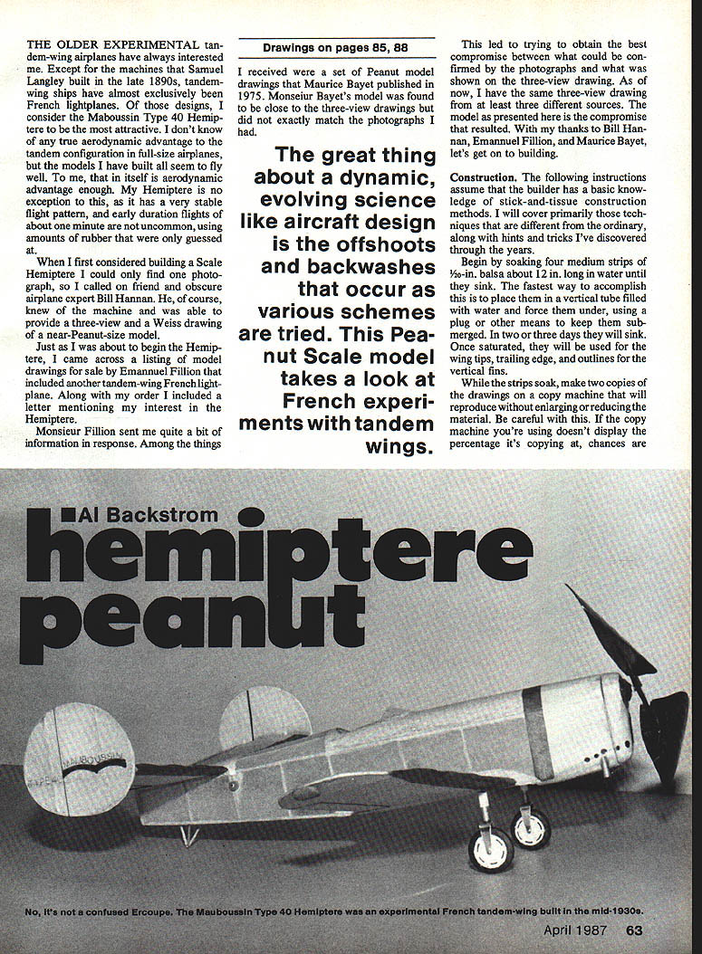
The older experimental tandem-wing airplanes have always interested me. Except for the machines Samuel Langley built in the late 1890s, tandem-wing ships have almost exclusively been French lightplanes. Of those designs, I consider the Maboussin Type 40 Hemiptère to be the most attractive.
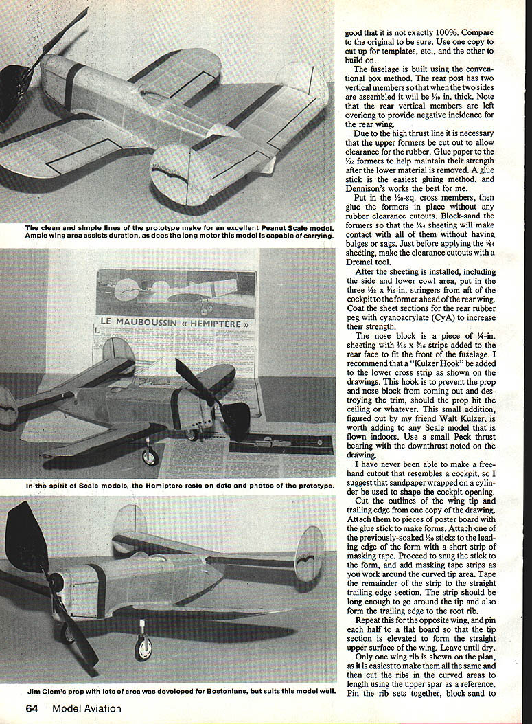
I don't know of any true aerodynamic advantage to the tandem configuration in full-size airplanes, but the models I have built all seem to fly well. To me, that in itself is aerodynamic advantage enough. My Hemiptère is no exception: it has a very stable flight pattern, and early duration flights of about one minute are not uncommon, using amounts of rubber that were only guessed at.
When I first considered building a scale Hemiptère I could only find one photograph, so I called on friend and obscure airplane expert Bill Hannan. He, of course, knew of the machine and was able to provide a three-view and a Weiss drawing of a near-Peanut-size model.
Just as I was about to begin the Hemiptère, I came across a listing of model drawings for sale by Emmanuel Fillion that included another tandem-wing French lightplane. Along with my order I included a letter mentioning my interest in the Hemiptère. Monsieur Fillion sent me quite a bit of information in response. Among the things I received were a set of Peanut model drawings that Maurice Bayet published in 1975. Monsieur Bayet's model was found to be close to the three-view drawings but did not exactly match the photographs I had.
The great thing about a dynamic, evolving science like aircraft design is the offshoots and backwashes that occur as various schemes are tried. This Peanut-scale model takes a look at French experiments with tandem wings.
This led to trying to obtain the best compromise between what could be confirmed by the photographs and what was shown on the three-view drawing. As of now, I have the same three-view drawing from at least three different sources. The model as presented here is the compromise that resulted. With my thanks to Bill Hannan, Emmanuel Fillion, and Maurice Bayet, let's get on to building.
Construction
The following instructions assume that the builder has a basic knowledge of stick-and-tissue construction methods. I will cover primarily techniques that differ from the ordinary, along with hints and tricks I've discovered through the years.
Materials and preparation
- Begin by soaking four medium strips of 1/20-in. balsa about 12 in. long in water until they sink. The fastest way is to place them in a vertical tube filled with water and force them under using a plug or other means to keep them submerged. In two or three days they will sink. Once saturated, they will be used for the wing tips, trailing edge, and outlines for the vertical fins.
- While the strips soak, make two copies of the drawings on a copy machine that will reproduce without enlarging or reducing the material. Be careful: if the copy machine doesn't display the percentage it's copying at, chances are it's not exactly 100%. Compare the original to be sure. Use one copy to cut up templates and other build forms, and use the other copy for parts alignment and building reference.
Fuselage (box method)
- The fuselage is built using the conventional box method. The rear post has two vertical members so that when the two sides are assembled they will be 1/8 in. thick (1/16 in. per side).
- Note: the rear vertical members are left overlong to provide negative incidence for the rear wing.
- Due to the high thrust line it is necessary that the upper formers be cut out to allow clearance for the rubber motor. Glue 1/32-in. paper to the formers to help maintain their strength after the lower material is removed.
- A glue stick is the easiest gluing method; Dennison's works best.
- Put in the 1/8-sq. cross members, then glue the formers in place. Block-sand the formers so the sheeting will make contact without bulges or sags.
- Just before applying the sheeting, make the clearance cutouts (for rubber) with a Dremel tool.
- After the sheeting is installed, including the side lower cowl area, put three 1/32 x 1/16-in. stringers from aft of the cockpit former to the former ahead of the rear wing.
- Coat sheet sections at the rear rubber peg with cyanoacrylate (CyA) to increase strength.
Notes on scale variations: you may see references to different sheeting thicknesses in other sources (e.g., 1/16-in. or 1/4-in.). Use materials appropriate to the model size you are building; the above dimensions suit the Peanut-size compromise described.
Nose block and prop retention
- The nose block is a piece of 1/16-in. sheeting with 1/16 x 1/16-in. strips added to the rear face to fit the front fuselage.
- I recommend adding a "Kulzer hook" to the lower cross strip shown on the drawings. The hook prevents the prop-nose block from coming out and destroying trim should the prop hit the ceiling. This small addition, suggested by my friend Walt Kulzer, is worth adding to any scale indoor model.
- Use a small Peck thrust bearing; the drawing notes the downthrust. The model is flown indoors, so a good thrust bearing and proper downthrust are important.
- I have never been able to make a freehand cockpit opening that looks right; use sandpaper wrapped around a cylinder to shape the cockpit opening.
Wing tips and trailing edges (forms)
- Cut the outlines for the wing tip and trailing edge from one copy of the drawing. Attach the pieces to poster board with a glue stick to make forms.
- Attach one of the previously-soaked 1/20-in. sticks to the leading edge form with a short strip of masking tape. Snug the stick to the form and add masking tape strips as you work around the curved tip area. Tape the remainder of the strip to the straight trailing-edge section. The strip should be long enough to go around the tip and also form the trailing-edge root.
- Repeat for the opposite wing, and pin each half to a flat board so that the tip section is elevated to form the straight upper surface of the wing. Leave until dry.
Wing ribs and assembly
- Only one rib outline is shown on the plan; it's easiest to make all ribs the same, then cut the ribs in curved areas to length using the upper spar as a reference.
- Pin the rib sets together, block-sand to exact shape, and cut the spar notches.
- Because ribs are of different thickness, stack them in order so any minor sanding deviations are progressive across the wing. Extra care here reduces sanding after assembly.
- Pin the ribs to the building board. Glue the leading and trailing edges to the ribs so they are level with the upper section of the ribs.
- When the wing is removed from the building board, trim off the excess on the outer ribs to the flat lower surface contour. On a normal wing tip this procedure produces a washed-out tip.
- Add trailing-edge fillet sections while the wings are on the building board.
- Add 1/20-in. fillers to the upper area of the root ribs so a flat can be sanded from the spar to the fillet trailing edge.
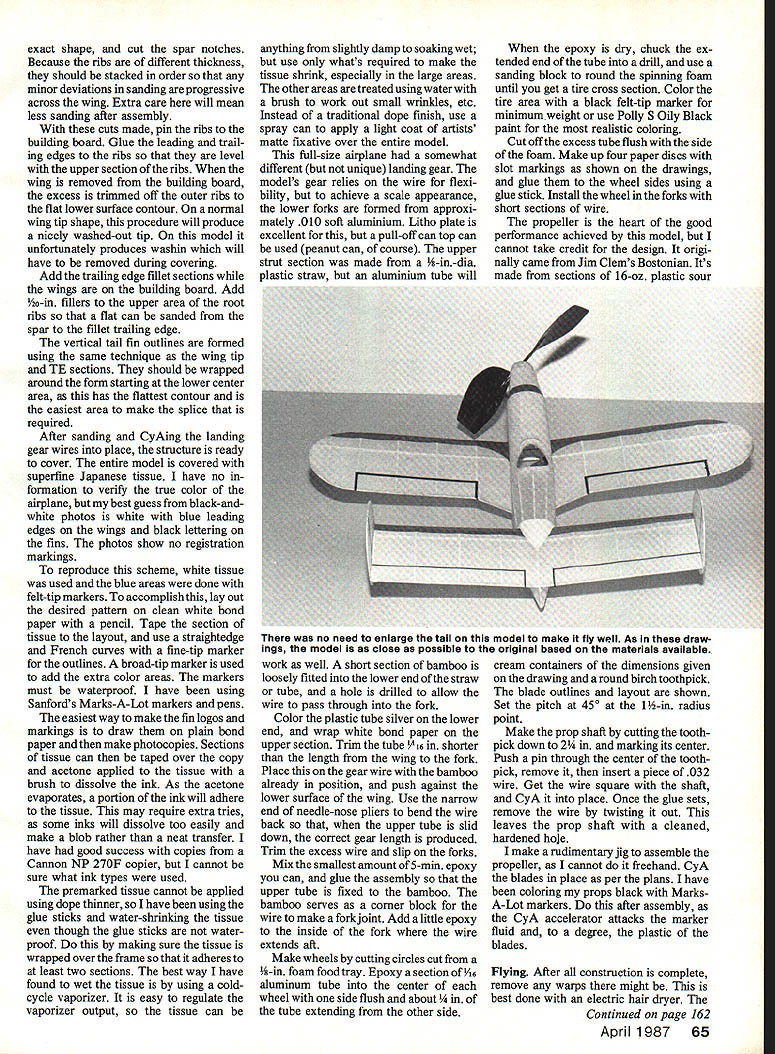
Vertical tail fins
- The vertical tail fin outlines are formed using the same technique as the wing tip and trailing-edge sections. Wrap them around the form starting at the lower center area (the flattest contour) and make the required splice there.
Landing gear and wheels
- After sanding and CyA-ing the landing gear wires into place, the structure is ready to cover.
- This full-size airplane had a somewhat different (but not unique) landing gear. The model's gear relies on the wire for flexibility, but to achieve a scale appearance the lower forks are formed from approximately .010-in. soft aluminum (tubing is excellent; a pull-off can top can also be used).
- The upper strut section was made from a 1/8-in.-dia. plastic straw; an aluminum tube can be used where practical.
- After the epoxy is dry, chuck the extended end of the tube into a drill and use a sanding block to round the spinning foam until you get a true cross section. Color the tire area with a black felt-tip marker for minimum weight or use Polly S Oily Black paint for the most realistic coloring.
- Cut off the excess tube flush with the side of the foam. Make up four paper discs with slot markings as shown on the drawings, and glue them to the wheel sides using a glue stick. Install the wheels on the forks with short sections of wire.
Covering and finishing
- The entire model is covered with superfine Japanese tissue.
- I have no definitive information on the true color of the full-size airplane, but my best guess from black-and-white photos is white with blue leading edges on the wings and black lettering on the fins. The photos show no registration markings.
- To reproduce this scheme: use white tissue and apply blue areas with waterproof felt-tip markers.
- Lay out the desired pattern on clean white bond paper with a pencil.
- Tape the section of tissue to the layout and use a straightedge and French curves with a fine-tip marker for outlines. Use a broad-tip marker for color areas.
- To make fin logos and markings: draw them on plain bond paper and make photocopies. Tape tissue over the copy and apply acetone with a brush to dissolve the ink so some ink transfers to the tissue as the acetone evaporates. This may require several tries; some inks dissolve too easily and will blob. I had good success with copies from a Canon NP 270F copier, but results depend on ink types.
- The premarked tissue cannot be applied using dope thinner, so I have been using glue sticks and water-shrinking the tissue even though glue sticks are not waterproof. Make sure the tissue adheres to at least two frame sections.
- The best way I have found to wet tissue is using a cold-cycle vaporizer. It is easy to regulate the vaporizer output so the tissue can be slightly damp to soaking wet—use only what's required to make the tissue shrink, especially in large areas. Use water with a brush for small wrinkles.
- Instead of a traditional dope finish, use a spray can to apply a light coat of artist's matte fixative over the entire model.
Propeller
- The propeller is central to the model's performance; the design originally came from Jim Clem's Bostonian.
- It's made from sections of 16-oz. plastic sour-cream containers (dimensions are given on the drawing) and a round birch toothpick.
- Set the pitch at 45° at the 1½-in. radius point.
- Make the prop shaft by cutting the toothpick down to 2½ in. and marking its center. Push a pin through the center of the toothpick, remove it, then insert a piece of .032 wire. Get the wire square with the shaft and CyA it into place. Once the glue sets, remove the wire by twisting it out—this leaves the prop shaft with a cleaned, hardened hole.
- I make a rudimentary jig to assemble the propeller as I cannot do it freehand. CyA the blades in place as per the plans.
- I color my props black with Marks-A-Lot markers after assembly; do this after the CyA sets, as CyA accelerator attacks the marker fluid and, to a degree, the plastic of the blades.
Flying and trimming
Preflight checks
- After construction is complete, remove any warps. The best method is an electric hair dryer:
- Turn on the dryer, twist the warp straight.
- Place the area in the hot air blast until the tissue wrinkles flatten out.
- Remove from the hot air and hold in the same position until cool.
- Repeat as necessary.
- Make up a motor of doubled 18-inch-long 3/32 FAI rubber for initial tests.
- Begin trimming under calm conditions. Give the model a two-fingered test glide to the ceiling with the prop removed:
- If it stalls, either remove a little incidence from the rear wing or add a little right thrust to the prop shaft.
- If it nose-dives, add a little up-elevator to the rear wing or increase downthrust.
First flights and adjustments
- I usually wind to 90% of maximum and let it climb out.
- When getting the model to fly on rubber, it will take experimenting with hook location and downthrust to obtain the best powered flight.
- The poorest flights have been with the downthrust shown on the drawing; a Peck-style thrust bearing helps quite a bit.
- Begin with glide tests: across a room, onto a bed, then at an indoor site with a launch height of about three feet. Increase launch height to a normal standing position as glide behavior improves.
- Install the motor and try about 200 turns. Adjust clay and downthrust as needed after powered tries.
- If the model tends to turn too tightly to one side, add a bit of clay to the opposite wing tip. In my build this also kept the rubber center close to the model CG so adding more rubber causes only a small trim change.
Trimming philosophy
- I think the best way to trim this model is to forget the tandem wings and just think of it as a model with a large tail and a CG about 60% MAC as marked on the side view in the drawing.
- Where I live (central Texas) calm indoor conditions are rare, so I often make first tests across the bedroom and onto the bed. With patience and careful incremental adjustments, good indoor flights can be achieved.
Final notes
- The scale model presented here is a compromise based on photographs, a three-view drawing, and published Peanut drawings. Expect to adapt materials and minor dimensions to your own available stock and desired scale fidelity.
- A Peck thrust bearing, Kulzer hook, careful rib stacking, and a well-made prop are the most important contributors to good performance.
- Have patience during trimming—small changes yield meaningful differences in flight.
Transcribed from original scans by AI. Minor OCR errors may remain.

