
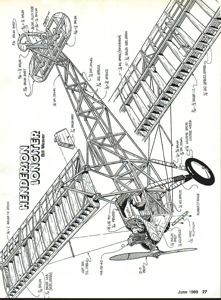
Henderson
Bill Weaver
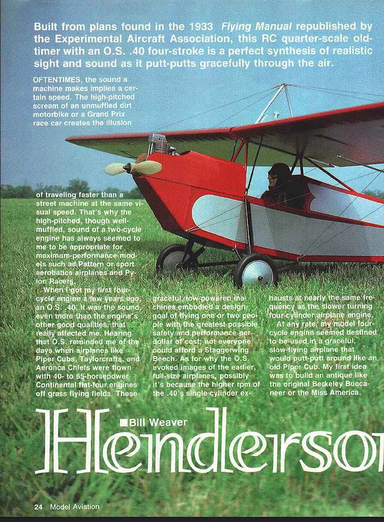
Built from plans found in the 1933 Flying Manual republished by the Experimental Aircraft Association, this RC quarter-scale old-timer with an O.S. .40 four-stroke is a perfect synthesis of realistic sight and sound as it putt-putts gracefully through the air.
Oftentimes the sound a machine makes implies a certain speed. The high-pitched scream of an unmuffled dirt motorbike or a Grand Prix race car creates the illusion of traveling faster than a street machine at the same visual speed. That's why the high-pitched, though well-muffled, sound of a two-cycle engine has always seemed appropriate for maximum-performance models such as Pattern or sport aerobatics airplanes and Pylon Racers.
When I got my first four-cycle engine a few years ago, an O.S. .40, it was the sound, even more than the engine's other good qualities, that really affected me. Hearing the O.S. reminded me of the days when airplanes like Piper Cubs, Taylorcrafts, and Aeronca Chiefs were flown with 40- to 65-hp Continental flat-four engines off grass flying fields. These graceful, low-powered machines embodied a design goal of flying one or two people with the greatest possible safety and performance per dollar; not everyone could afford a Staggerwing or Beech. The O.S. evoked images of the earlier, full-size airplanes perhaps because the higher rpm of the .40's single cylinder exhausts at nearly the same frequency as the slower-turning four-cylinder airplane engine.
My model four-cycle engine seemed destined to be used in a graceful, slow-flying airplane that would putt-putt like an old Piper Cub. Initially I considered building an antique like the original Berkeley Buccaneer or the Miss America. Then it occurred to me: why not make a seven- to eight-foot-span model of an old lightplane or home-built, using the same type of construction, the same flying weight and wing loading as the antique models? It would be the perfect synthesis—an airplane appropriate to the four-cycle sound that would also look real. That decided, I scanned my memory for lightplanes and home-builts I liked, and remembered Les Long's Henderson Longster.
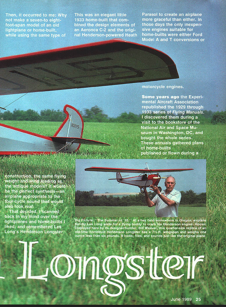
Les Long's Longster (1933) was an elegant little home-built that combined the design elements of an Aeronca C-2 and the original Henderson-powered Heath Parasol to create an airplane more graceful than either. In those days the only inexpensive engines suitable for home-builts were Ford Model A and T conversions or motorcycle engines.
Some years ago the Experimental Aircraft Association republished the 1929–1933 series of Flying Manuals. I discovered them at the National Air and Space Museum bookstore and bought the series. These annuals gathered plans of home-builts published or flown during a particular year and are a wonderful source of detail drawings for scale modeling. Luckily, the 1933 Flying Manual included working drawings for the full-size Longster, and my prototype model is scaled from the plans, dimensions, photos, and text in its pages.
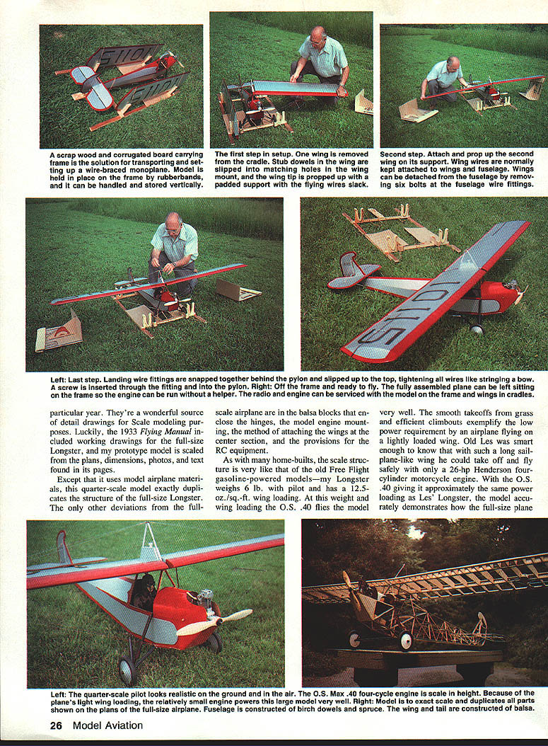
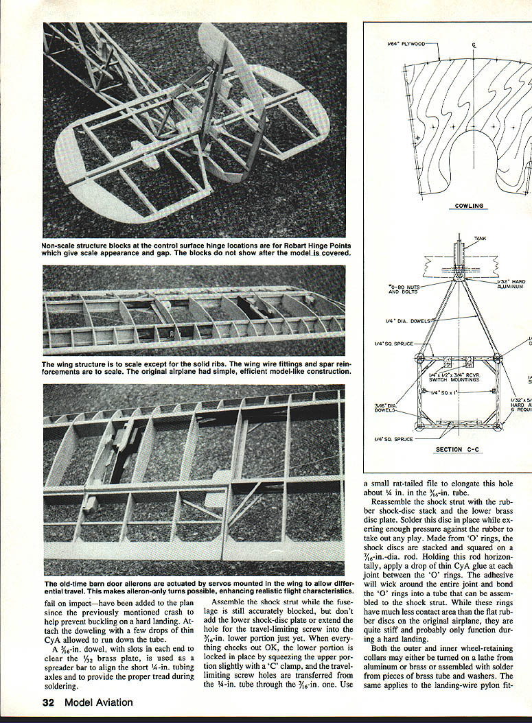
Except for using model-airplane materials, this quarter-scale model exactly duplicates the structure of the full-size Longster. The only other deviations are in the balsa blocks that enclose the hinges, the model engine mounting, the method of attaching the wings at the center section, and the provisions for the RC equipment.
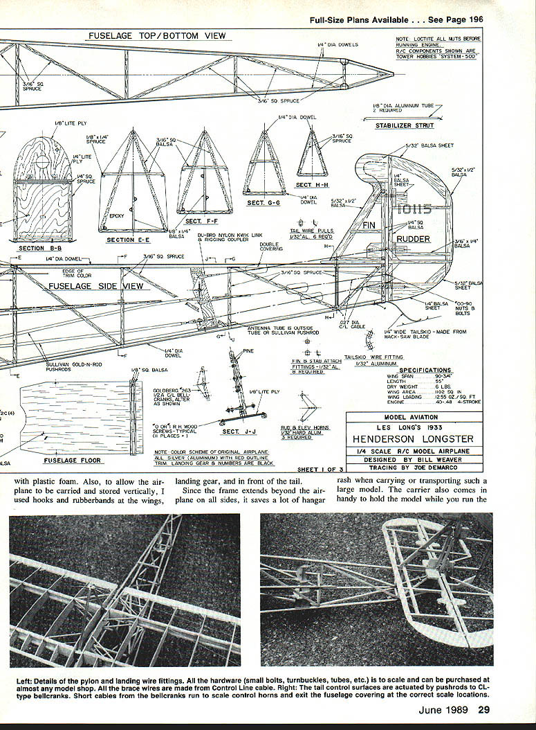
As with many home-builts, the scale structure is very like that of the old free-flight gasoline-powered models—my Longster weighs 6 lb with pilot and has a 12.5 oz/ft² wing loading. At this weight and wing loading the O.S. .40 flies the model very well. The smooth takeoffs from grass and efficient climbouts exemplify the low power requirement of an airplane flying on a lightly loaded wing. Old Les was smart enough to know that with such a long sailplane-like wing he could take off and fly safely with only a 26-hp Henderson four-cylinder motorcycle engine. With the O.S. .40 giving approximately the same power loading as Les' Longster, the model accurately demonstrates how the full-size plane will perform in the air.
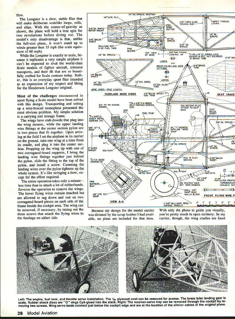
The model is a slow, stable flier and will make deliberate, scale-like loops, rolls, and slips. With the center of gravity shown the plane will hold a true spin for about two revolutions before diving out. The model's disadvantage, unlike the full-size plane, is that it won't stand up to winds greater than about 15 mph (scale equivalent about 60 mph).
The Longster exactly scales because it replicates a very simple airplane and can't be expected to rival world-class scale models of fighters or trimotor transports. Rather, it is an everyday sport flier intended as an expression of respect and liking for the Henderson Longster original.
Transporting and carrying frame
Transporting and setting up a wire-braced monoplane presented an obvious problem; a simple solution is a carrying/storage frame.
- Wings have stub dowels that plug into the wing mounts.
- The upper landing-wire fittings and the center-section pylon are in two pieces that fit together.
- Upon arriving at the field, set the airplane on its carrier and take the wings from their cradle; plug in the center section.
- Prop up the wing tip. Two corrugated-board supports bring the landing-wire fittings together just behind the pylon; slide the fitting up over the top of the pylon and install the screw. Camming the landing wires over the pylon tightens up the whole system. It's like stringing a bow except the effort required is small — the entire operation takes a minute or less.
- Reverse the operation to remove the wings. The lower flying wires remain attached and are allowed to sag down to rest on two corrugated-board pieces placed alongside the frame beside the cockpit area; the wing can then be removed and stored vertically on the frame.
My carrier was dictated by scrap lumber I had available, so no plans are included. In my carrier the wing cradles are lined with plastic foam. To allow the airplane to be carried and stored vertically I used hooks and rubber bands at the wings, landing gear, and in front of the tail. Since the frame extends beyond the airplane on all sides, it saves a lot of hangar rash when carrying or transporting such a large model. The carrier also holds the model while you run the engine or check the radio; the engine and radio can be serviced while the model sits in the frame.
Suitable engines
- O.S. .40
- O.S. .48 Surpass
- Saito .40 or .45
The Longster is designed around engines in this power and weight range. Don't substitute a .60 or larger engine: the model doesn't need the power, would be out of scale, and the extra weight would throw it out of balance. The surplus power would destroy the whole concept.
Construction
I'll limit myself to general descriptions of the construction procedures used, explaining the underlying rationale and some building philosophy. There should be enough interesting detail to satisfy those who like to build as well as fly.
Wing, aileron, and tail
- Since they're made primarily of balsa, the wing and tail can be completed most rapidly using cyanoacrylate (CYA) adhesives. If you're allergic to CYA, white glue will work. (Editor: anyone with an allergy to ordinary CYA should try Hot Stuff's UFO.)
- After drilling the balsa for the fitting-screw holes, apply a drop of thin CYA to each side of the holes, then ream with the original drill to remove hardened fibers. This produces a nice, hard-walled hole to take the screw bearing loads. The 00-90 and 0-80 screws are the scale equivalents of the 1/8- and 1/4-in. bolts used on the original.
- The working brace wires put the maximum bending loads at the wire attach points rather than at the center as with a cantilevered wing. The flight loads are distributed at several points along the wing spars. The 70-lb test cables assure that the wing can support any flight load it will encounter.
- Locating aileron servos in the wing makes it simple to provide travel differential. If you run a 2-56 tap through the servo nylon Qwik-Link, the pushrod can be more easily turned from outside the wing covering to adjust aileron neutral. The location of the servo wires that run down to the connectors in the cockpit duplicates that of the aileron control wires in the full-size ship.
- The old-time barn-door ailerons are actuated by servos mounted in the wing to allow differential travel. This makes aileron-only turns possible, enhancing realistic flight characteristics.
Fuselage
A central problem in reproducing a welded steel-tube fuselage frame in wood is that the crossmembers, longerons, and diagonals that form the truss will be subjected to either tension or compression loads depending on how the structure is loaded or twisted. Since the welded structure is a unit, it's unlikely that one of the tube members will fail in tension, although the structure can buckle under compression.
In a wood-frame structure the joints between members and at longeron breaks depend on glue strength to take tension loads. In balsa structures the glue joints under tension will be no stronger than the soft porous wood. After testing with pieces of dowel and spruce, I was unimpressed with the strength of hardwood glue joints. Ambroid proved just slightly better than CYA or white glues and was chosen for this project. All glue tests involved applying several coats to form fillets at the joints.
I was especially concerned about the area forward and under the wings where flight loads from the wing wires, engine thrust loads, and landing loads try to pull the joints apart. Lacing these joints with strong carpet thread provided a happy, lightweight solution. After the fuselage was completely glued, I hand-drilled 1/16-in. holes at the joints with a pin vise. I connected the two sides at the corner joints with grooves cut by an X-Acto knife so that the thread would pass under the landing-gear down tubes without showing through the covering.
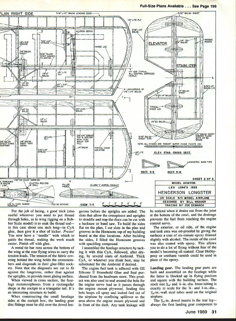
A good trick for lacing: soak about a 1-inch length of thread in CYA glue, then give it a shot of kicker. Presto—you now have a “needle” to guide the thread, making the work much easier. Finish off with glue.
A metal tie bar runs across the bottom of the wing at the rear flying wires to carry the tension loads. The tension of the fabric covering behind the wing holds the crossmembers and diagonals in their glue-fillet sockets. Note that the diagonals are cut to fit against the longerons, rather than against the uprights, to provide more gluing surface.
When viewed in cross section the fuselage metamorphoses from a rectangular shape at the cockpit to a triangular tail—an interesting structure to build.
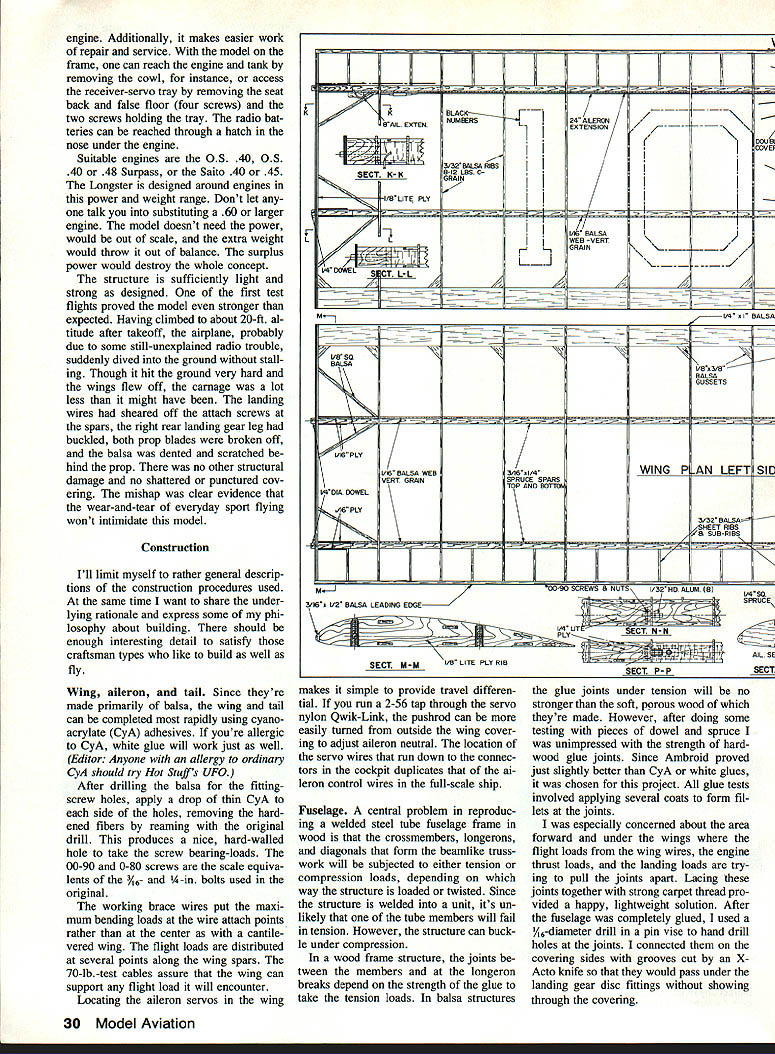
When constructing the small fuselage sides at the cockpit box, slide the landing-gear disc fittings over the dowel longerons before adding the uprights. The slots that allow crosspieces and uprights to straddle and trap the discs can be cut with a hacksaw or band saw. To build the sides on the plan, cut slots in the plan and grooves in the Homosote top of the building board at the disc locations. After building the sides, fill the Homosote grooves with sparking compound.
Assemble the fuselage structure by tacking with thin CYA, followed after drying by several coats of Ambroid. Thick CYA or your preferred adhesive may be substituted if desired.
The engine fuel tank is adhered with GE Silicone II Household Glue and Seal. This product was also used to seal around the hole for the engine servo lead as it passes through the thin one-ply plywood. Sealing the hole keeps oil spray and leaked fuel out of the airplane by confining spillover to the area above the engine-mount plywood and in front of the dash. Any tank leakage will be noticed when it drains from the joint at the bottom of the cowl, and the drainage prevents fuel from reaching the engine or control servo.
The exterior (oil side) of the engine and tank area was oil-proofed by giving the surfaces a coat of six-minute epoxy thinned slightly with alcohol. The inside of the cowl was also coated with epoxy. This lets you do a lot of flying without fear of the model becoming oil soaked. Clear Hobby-Poxy or urethane varnish could be used in place of epoxy.
Landing gear
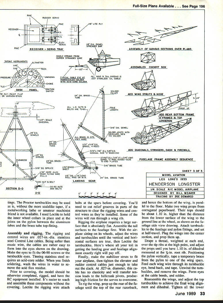
- Build and assemble landing-gear parts on the fuselage while it is blocked up in flying position and square with the building surface. The stock 1/4-in. and 3/16-in. dia. brass tubing is exactly to scale for the 3/4- and 1-in.-dia., 1/8-in.-wall steel tubes used on the original airplane.
- The 1/2-in. dowel inserts in the rear leg — always the first landing-gear component to fail on impact — have been added to the plan since the previously mentioned crash to help prevent buckling on a hard landing. Attach the doweling with a few drops of thin CYA allowed to run down the tube.
- A 3/16-in. dowel, with slots in each end to clear the 3/32-in. brass plate, is used as a spreader bar to align the short 1/4-in. tubing axles and to provide the proper tread during soldering.
- Assemble the shock strut while the fuselage is still accurately blocked, but don't add the lower shock-disc plate or extend the hole for the travel-limiting screw into the 3/16-in. lower portion yet. When everything checks out, lock the lower portion in place by squeezing the upper portion slightly with a C-clamp, and transfer the travel-limiting screw holes from the 1/4-in. tube through the 3/16-in. one. Use a small rat-tailed file to elongate this hole about 1/4 in. in the 3/16-in. tube.
- Reassemble the shock strut with the rubber shock-disc stack and the lower brass disc plate. Solder this disc in place while exerting enough pressure against the rubber to take out any play. The shock discs, made from O-rings, are stacked and squared on a 7/64-in. dia. rod. Holding this rod horizontally, apply a drop of thin CYA at the joint between O-rings; the adhesive will wick and bond the O-rings into a tube that can be assembled to the shock strut. While these rings have much less contact area than the flat rubber discs on the original airplane, they are quite stiff and probably only function during a hard landing.
- Both outer and inner wheel-restraining collars may either be turned on a lathe from aluminum or brass or assembled with solder from pieces of brass tube and washers. The same applies to the landing-wire pylon fittings.
- The Proctor turnbuckles may be used as is, without the more scale-like taper, if a metalworking lathe or amateur machinist friend is not available. I used Loctite to hold the inner wheel collars in place and at the joints on the pylon between the aluminum tubes and the brass tube top fitting.
Assembly and rigging
- The rigging and control wires are .027-in. dia. stainless-steel control-line cables. Being softer than music wire, the cables are easy to form into the eyes shown on the drawings. Make the eyes to fit the 00-90 screws on the turnbuckle eyes. Tinning stainless steel requires an acid-core solder; when you finish soldering, wash the wires in water to remove the acid flux residue.
- Prior to covering, the model should be completed, rigged, and have the RC equipment installed. It's easier to reach and assemble these components without the covering. Loctite the rigging wire attach bolts at the spars before covering. You'll need to cut relief grooves in parts of the structure to clear the rigging wires and control wires as they're installed; some wires will run through a wing rib.
- Rigging requires a large surface that is absolutely flat. Assemble the tail surfaces to the fuselage first. With the airplane sitting on its wheels, adjust the wires and turnbuckles until the vertical and horizontal surfaces are true, then Loctite the turnbuckles. This is where careful landing-gear and fuselage alignment pays off.
- Make the stabilizer struts to fit your airplane, then tighten the elevator and rudder control cables just enough to take out the slack. At .027-in. diameter this cable has no elasticity and will transfer tendon loads to the bellcrank pivots, producing high friction for the servos to overcome if overtightened.
- To rig the wing, prop up the rear of the fuselage until the top of the rear razorback, and hence the bottom of the wing, is parallel to the floor. Make two wing props from corrugated cardboard. Their tops should be about 1.10 in. higher than the distance from the lower surface of the wing to the ground line at the wheel, as shown on the fuselage side-view drawing. Attach turnbuckles to the fuselage and pylon fittings and set at half travel. Plug the pylon into the center section and prop them up.
- Drape a thread, weighted at each end, over the tip ribs at the high point and adjust the props until you have 1.10 in. of dihedral measured at the 1/8-in. root rib. Position the pylon vertically, tape a temporary brace from the pylon to one wing spar, feed each wing wire through its turnbuckle eye, bend back, and tape. Form the wire eyes to fit the turnbuckle screws, solder the joints with acid-core solder, and wash the flux off the wires.
- Reassemble the wings, adjust the top turnbuckles to achieve final wing alignment and dihedral, tighten all the turnbuckles, then remove the temporary bracing and recheck alignment. Turnbuckles should be tightened just enough to take out slack. You should be able to sense the tightness in the top wires when plucked—each pair of top wires has four semislack wires pulling against it. Adjust the top and bottom rear-spar wires to give 1/16-in. washout at the tip ribs.
- Hold the wire-eye ends when adjusting turnbuckles to prevent the cables from winding up due to thread friction, which would throw the two thread engagements off balance and predispose the cable to unwinding. When happy with the adjustment, apply Loctite to both threads of each turnbuckle.
- Bind the 1/8-in. spreader bars to the wires with thread, cement them, and paint them silver. Position the bars at the intersection of the "X" brace wires to keep the wires from touching and causing radio noise. This fixed wing rigging can be folded or removed without worry and will return to its proper position when replaced just as if solid struts had been used.
Covering
- Use fabric such as Coverite or Sig Koverall. Both the texture and finish of plastic films would clash with the character of this airplane. The silver Permagloss Coverite used on the prototype is no longer made. White Super Coverite finished with a spray can of your preferred silver model paint is a good alternative. I used Aerogloss Stearman red for trim.
- The numbers were cut from black Coverite Graphic Trim Sheets, slid into place on soapy water, and rubbed down. While Coverite bonds well to itself, it needs extra adhesion where it contacts wood; use Balsarite or Sig Six-It on wood surfaces.
- Don't cover the rear fuselage bottom until the control-wire openings are located in the side covering and the wires threaded through. Refer to the plans for the location of the holes for the landing wires in the wing top covering. Thread the landing wires through the loose covering before ironing it into place. Errors can be corrected by double-covering patches which are slid over the wires and ironed down after final assembly.
- The attach points for the "X" brace wires are at two triangular openings on the bottom of the wing, inboard of the spars. The Pyralin doors that covered the wire-attach points on the full-size Longster are simulated on the model by thin, transparent plastic with notches to clear the wires.
Balance and final items
- Balance the model at the point shown on the drawing on a 1/2- or 5/8-in.-dia. dowel or rod. You probably have about 1/4 in. latitude fore or aft of the indicated point, but any greater deviation may cause trouble. Differences in engine weight, RC equipment, covering and finish, etc., could contribute to excess weight at the nose or tail. Compensate by substituting 800 or 500 mAh batteries for the 1,100 mAh ones shown if the model is nose-heavy, or by adding lead before installing the batteries if tail-heavy. The small-scale tail surfaces require this forward center-of-gravity location for good stability and control.
- Paint the false floor and seat back black, followed by Sig Flat-Coat. Make the gas tank of 1/16-in. sheet balsa, cover with tissue, and apply a few coats of Sig Lite-Cote. A plastic cap from a large toothpaste tube served as my gas cap. Spray the tank assembly silver and glue it in place. The tank occupies a convenient point up front during wing assembly. Though the tank is trapped by the cowl, the cowl can be removed to service the engine and tank if necessary.
- The pilot is a quarter-scale full-body figure made from a DGA Designs kit. As constructed on the model it was necessary to modify the pilot: the wing limited view into the cockpit, so the pilot was cut out at the waist and elbows and a false floor was installed. This helps keep the pilot from being blown, similar to the turned-up sheet-metal lip under the windshield on the full-size airplane. No windshield is indicated in the original plans or photos. Quite possibly, at a cruising speed of 60–65 mph the wind was used as an airspeed indicator and for judging turn coordination.
Durability
One of the first test flights proved the model stronger than expected. After climbing to about 20 ft, the airplane—probably due to unexplained radio trouble—suddenly dived into the ground without stalling. Though it hit very hard and the wings flew off, the damage was limited: the landing wires sheared off the attach screws at the spars, the right rear landing-gear leg buckled, both prop blades were broken off, and the balsa was dented and scratched behind the prop. There was no other structural damage and no shattered or punctured covering. The mishap was clear evidence that everyday sport flying won't intimidate this model.
Conclusion
The Longster exactly replicates a very simple airplane and cannot be expected to rival world-class scale fighters or transports. Rather, it is an everyday sport flier intended as an expression of respect and liking for the original Henderson Longster. Most challenges encountered in sport-flying scale models have been solved in this design, and the results are very satisfying.
Transcribed from original scans by AI. Minor OCR errors may remain.

