
HENRY T
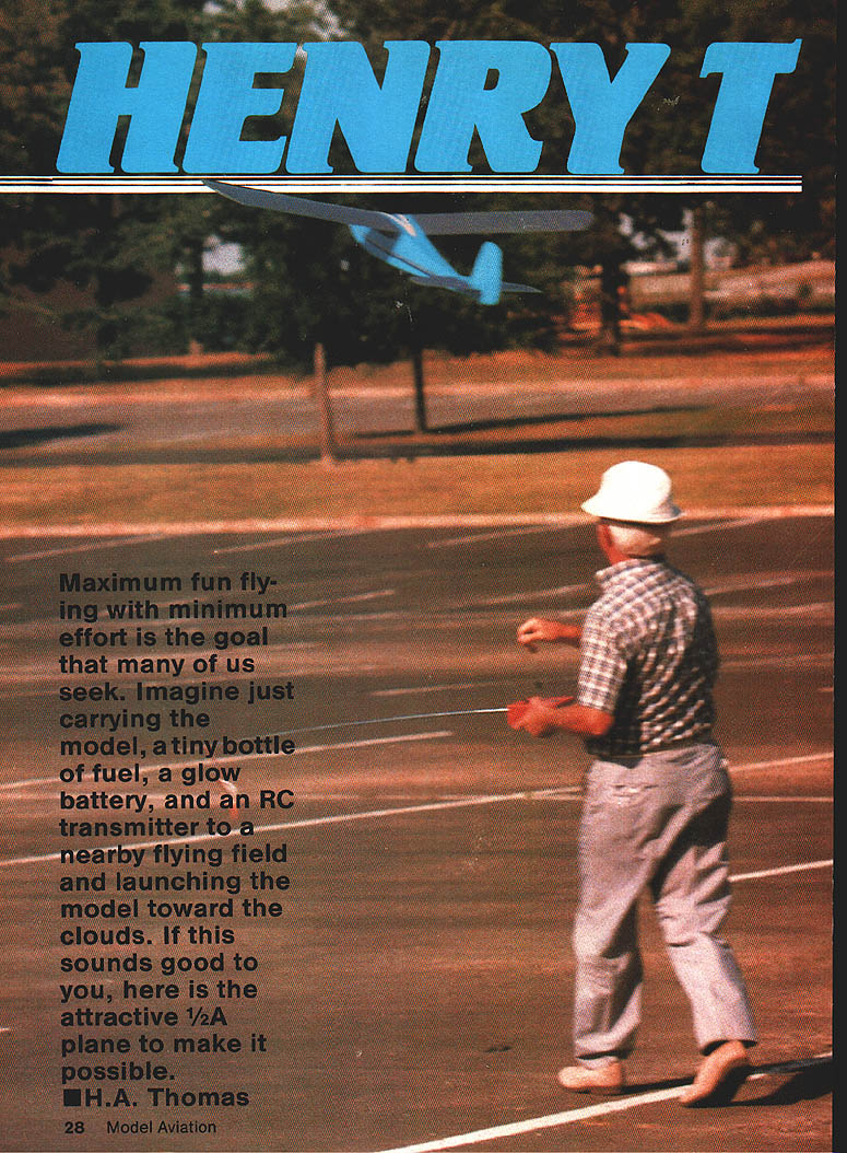
Maximum fun flying with minimum effort is the goal many of us seek. Imagine carrying only the model, a tiny bottle of fuel, a glow battery, and an RC transmitter to a nearby flying field and launching the model toward the clouds. If this sounds good to you, here is the attractive 1/2A plane to make it possible.
This model is named for H.A. Thomas and for its similarity in purpose to Henry Ford's Model T car — remembered for economy and dependability. While not the simplest 1/2A RC model you could build nor the smallest, it has features that give fine stability, the capability of soaring in light air, good takeoff and landing characteristics, and a rugged yet lightweight structure. The original model shown here had logged more than 275 flights, many from very small fields.
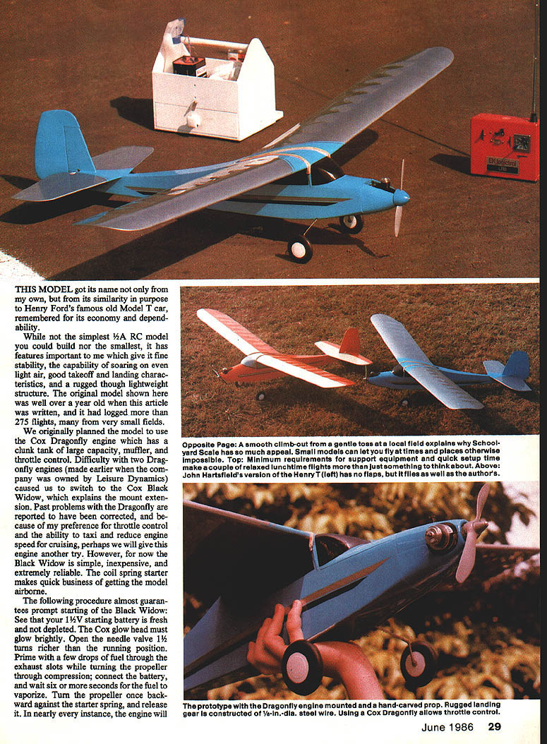
We originally planned the model to use the Cox Dragonfly engine (large clunk tank, muffler, throttle). After difficulty with the Dragonfly we switched to the Cox Black Widow, which explains the mount extension. The Black Widow is simple, inexpensive, and extremely reliable; the coil-spring starter makes quick business of getting the model airborne.
Black Widow starting procedure (almost guarantees prompt starting):
- Ensure your 1.5-V starting battery is fresh.
- Make sure the Cox glow head glows brightly.
- Open the needle valve 1¼ turns richer than the running position.
- Prime with a few drops of fuel through the exhaust slots while turning the prop through compression; connect the battery and wait six or more seconds for the fuel to vaporize.
- Turn the prop once backward against the starter spring and release it.
In nearly every instance the engine will start promptly.
The wing flaps are optional. They are ground-adjustable by twisting the clevis at the flap horn. Small down-flap (no more than 3/8 in.) can slow airspeed, shorten takeoff runs, and aid small-field flying. Both versions (with and without flaps) flew perfectly from the start with only minute trimming necessary.
Flight pack (Goldberg flight box) essentials:
- Can of Cox fuel
- Small rubber fuel bulb
- Compact 1½-V battery with Cox connector
- Spray bottle of cleaner
- Rubber bands, spare props, spare glow heads
- Pliers, screwdriver, Cox head wrenches
My Henry T uses a three-channel EK brick (receiver and two servos in a compact unit). An inexpensive two-channel, two-stick radio would suffice. The flight battery is 500 mAh for ample flight time. Even so, the model weighs only about 30 oz. ready to fly. Span and chord are 55 in. and 7¼ in., giving about 360 sq. in. area and wing loading around 12 oz./sq. ft. The cowl contributes measurably to the clean lines and to performance; please do not omit it.
Fuselage construction
Select medium-light balsa for all parts except where noted. Trace the fuselage outline on 3/32-in. sheet and cut two sides and a pair of 1/32-in. plywood interior doublers. Glue these and tape them to the fuselage sides with your favorite adhesive (we used Elmer's woodworking glue). Make the 1/8-in. plywood firewall with a 1/8-in. doubler and the two main fuselage formers, keeping everything square.
Tools that make assembly easier:
- Dremel scroll saw for cutting curved balsa and plywood parts.
- Dremel table saw with fine-tooth blade for ripping sheet balsa and thin plywood.
- 1/8-in. drill in a bench mount, ideal with a sanding disc or drum for shaping/hollowing blocks.
- A series of large sanding blocks (coarse, medium, fine).
- Pins, clothespins, small clamps, masking tape.
Install the plywood and balsa interior doublers inside the cabin and along the fuselage sides. Note how the 1/32-in. balsa is feathered to bridge the ledge left by the plywood doublers.
Bend the 3/16-in. landing-gear wire and make its mounting lamination of 1/8-in. balsa with 1/32-in. plywood sides. Epoxy the gear wire into this unit; glue and clamp the plywood parts, checking axle alignment.
Assemble the fuselage about the two main formers at the wing leading edge (LE) and trailing edge (TE). Make everything square, holding parts in position with masking tape. Bend and clamp the sides to meet the firewall; use epoxy here. Add triangular braces inside the fuselage/firewall joints and balsa doublers at the top and bottom fuselage edges between the first former and the firewall. Glue and clamp the landing gear unit in front of the former at the wing-LE location.
Bring the rear ends of the fuselage together; glue and tape as necessary. Add the remaining formers which attach to the vertical balsa strips inside the fuselage at each former station. Note the slight reflex inward curve of the fuselage between the wing and tail. Add a 3/16-in. dowel for wing rubbers at the TE location, reinforcing and gluing this area carefully.
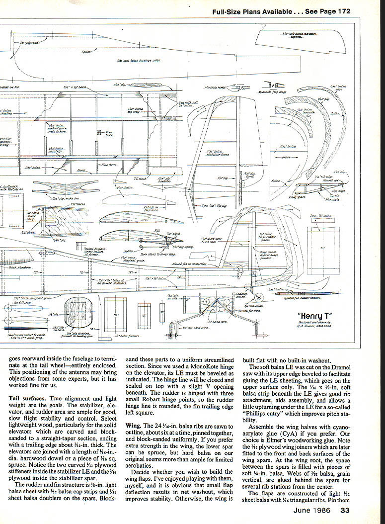
Wing hold-down: use double-prong wing hooks (two staggered prongs) that penetrate both balsa and plywood for security and reduce cutting of the wing rubbers. These hooks are easily bent with round-nose pliers. Attach them with epoxy inside and out. The recessed rear wood hold-down dowel provides a knock-off feature for rough landings.
Add the 1/8-in. plywood bottom covering between the landing gear and firewall, beveling the outer edges and gluing, pinning, and taping the plywood in place. Epoxy the Goldberg nylon tail-wheel fitting to the fuselage and solder the washers necessary to hold the 1/16-in. steel tail-wheel wire to the fitting and to secure the 3/8-in.-dia. tail wheel. The upper part of the wire is bent back to penetrate the rudder for steerable tail-wheel control. Solder washers as needed to secure the Williams Bros. Smooth Contour 2-1/4-in. wheels with concealed hubs. You now have a durable, neat undercarriage positioned for good ground handling.
Enclose the bottom of the fuselage with 3/32-in. balsa sheet with the grain placed diagonally. Leave the fuselage top open until pushrods are installed.
Radio installation: our "brick" was mounted with screws on cross members made of 3/16-in. sq. hard balsa capped with 1/16-in. plywood. Photos show a simple mount on the right fuselage side for a third servo. Mount receiver and servos where necessary for correct final balancing. Fit Sullivan flexible pushrods from servo locations rearward to pass through the fuselage sides beneath the stabilizer: rudder pushrod exits left, elevator on the right. Make long, angular outlets, trimming the outside tube flush with the fuselage side. Anchor the pushrods at several locations inside the fuselage securely with balsa crescents and epoxy.
Cover the fuselage top with diagonally fitted 3/32-in. balsa, shimming to allow a 1/16-in. edge so the wing trailing edge fits flush. The rounded cutout for access to the rear wing dowel should have 1/16-in. plywood reinforcement inside to prevent wear when attaching rubber bands.
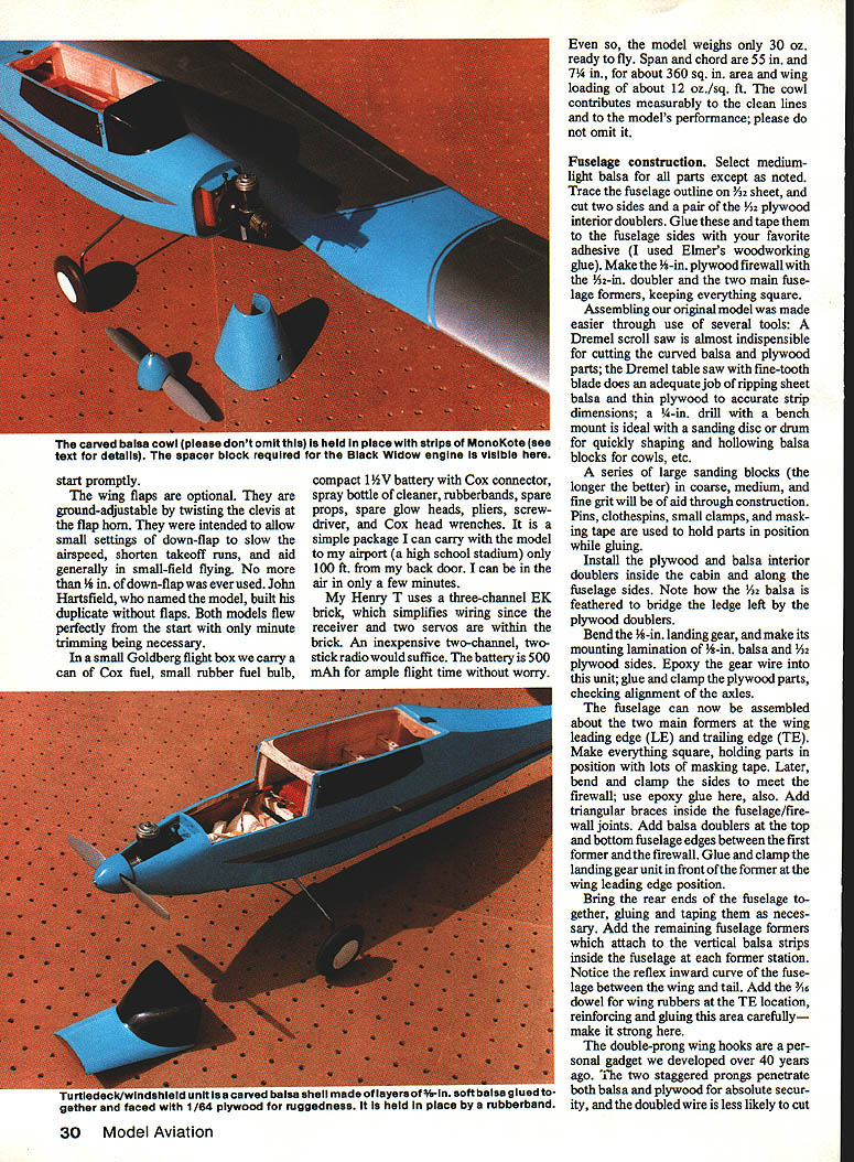
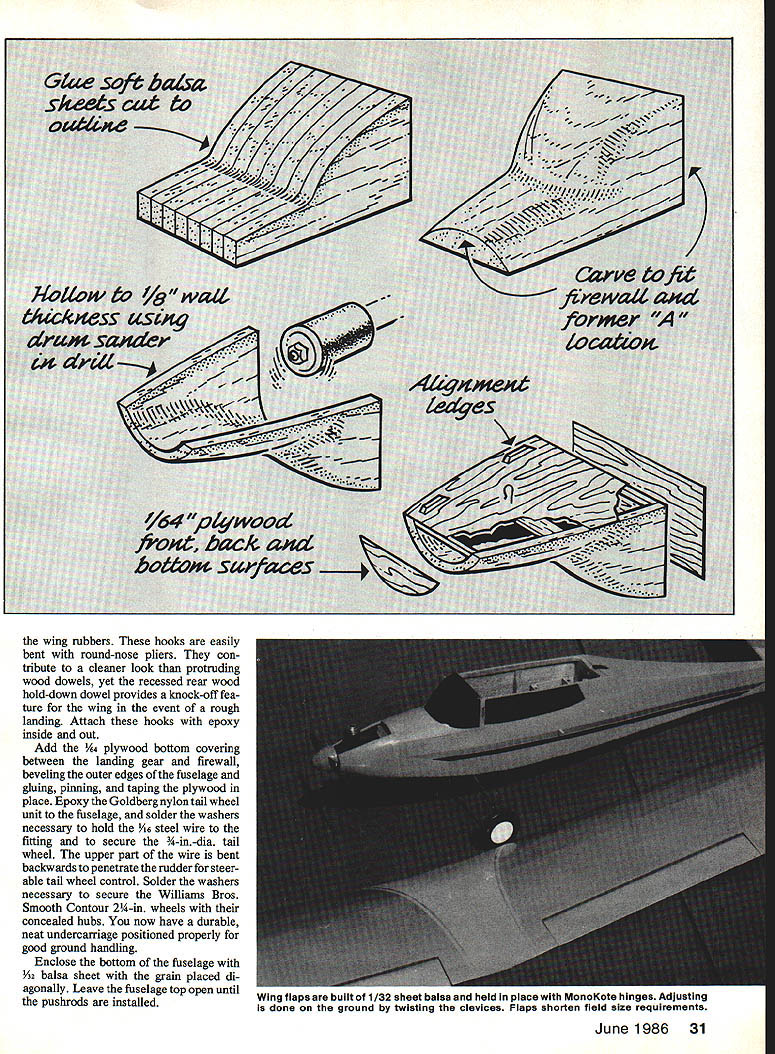
The front turtledeck and windshield are a single balsa part carved to desired curvature. Glue up the block of 3/8-in. soft balsa layers, carve and sand to fit, then hollow to about 1/8-in. wall thickness using a bench-mounted drill with a 1-in.-dia. drum sander. Sand off thin layers at front, rear, and base to accept 1/8-in. plywood surfaces for a perfect fit. Install cross members and a cross member to secure the hold-down rubberband hook before the bottom plywood piece is glued in place. Fit top of windshield later to the completed wing LE and add small balsa fillers to blend lines.
Antenna installation (clean, enclosed method): from the receiver outlet, pass the antenna forward through short cemented pieces of outer flex-rod (as guides) to the firewall, cross to the opposite fuselage side, then run back along the fuselage side to the fin and exit through a drilled hole at the fin leading edge. The remainder runs rearward inside the fuselage to terminate at the tail wheel — entirely enclosed. This keeps the antenna tidy and away from inboard radio components.
Tail surfaces
True alignment and light weight are the goals. The stabilizer, elevator, and rudder are ample for good slow-flight stability and control. Select lightweight wood, particularly for the solid elevators, which are carved and block-sanded to a straight-airfoil section with a trailing edge about 1/16-in. thick. The elevators are joined with a length of 1/16-in. hardwood dowel or a piece of 1/16-in. square spruce. Note the two curved 3/32-in. plywood stiffeners inside the stabilizer LE and the 1/16-in. plywood inside the stabilizer spar.
The rudder and fin structure is 1/8-in. light balsa sheet with 1/32-in. balsa cap strips and 1/4-in. balsa doublers on the spars. Block-sand these parts to a uniform streamlined section. If using a MonoKote hinge on the elevator, the LE must be sealed as indicated: hinge line closed and sealed on top with a slight V opening beneath. The rudder is hinged with three small Robart hinge points; round the rudder hinge line and leave the fin trailing edge square.
Wing
The wing uses 24 1/16-in. balsa ribs sawn to outline, pinned together in small stacks and block-sanded uniformly. If you prefer extra strength, the lower spar can be spruce; hard balsa on the original proved ample for limited aerobatics.
Decide whether to build flaps. Small flap deflection produces net washout, improving stability. Otherwise build the wing flat with no built-in washout.
The soft balsa LE is cut and beveled to accept LE sheeting, which goes on the upper surface only. A 1/16-in. soft balsa strip beneath the LE gives good rib attachment, aids assembly, and allows a slight upturn under the LE for a "Phillips entry" improving pitch stability.
Assemble main halves using CyA if you prefer; we use Elmer’s woodworking glue. Note the 1/32-in. plywood wing joiners which are later fitted to the front and back surfaces of the main spars. At the wing root, fill the space between the spars with pieces of soft 1/8-in. balsa. Glue 1/32-in. balsa webs (grain vertical) behind the spars for several rib stations from the center.
Flaps: construct of light 3/32-in. sheet balsa with 1/16-in. triangular ribs. Pin them over the building board while glue sets. Ailerons are 1/8-in. sheet with cap strips and 1/32-in. triangular ribs. Hinge with tape or Robart hinges as you wish.
Sand ribs and sheeting and apply 1/32-in. sheeting to the top between the spars, leaving bottom sheeting off for access to servos. Leave wingtips unsheeted until after sanding and finishing. Build in washout by setting trailing edges of outboard ribs 1/16-in. higher than inboard ribs or slightly twist when joining wing halves.
Cut and install the special tip rib to the upper spar and rib doublers outside the last full rib which serves as a cementing ledge. When tips are dry, glue them in position, pinning and taping as necessary. Add 3/32-in. balsa tip edges, small rear spar extensions, and fit the 1/8 x 1/4-in. lower spar extension which angles upward to the tip end.
Join the wing halves (plywood joiners fix the dihedral angle), and fit soft 1/32-in. sheet leading-edge sheeting using lots of masking tape. Add upper rib cap strips—none on the lower surface. Cover the center section top with 1/32-in. sheet balsa as indicated. Block-sand the entire wing. Add 1/64-in. plywood TE reinforcement under the trailing edge and 1/32-in. plywood strip to the wing LE where it fits against the windshield.
Back at the fuselage: temporarily mount the wing to block in small balsa pieces behind the plywood LE reinforcement. Carve and sand the windshield rear edge into the wing LE for a smooth continuous line. Use sanding block and spackling paste to make a neat job.
Wing tips: bevel the balsa tip edges upward to almost meet the plywood tip doubler. Add the 1/32-in. balsa lower tip part at the LE and fair it in. Make a 1/8 x 1/32-in. cap strip for the bottom of the tip rib. With final fine sanding, the wing frame is complete.
Engine installation and cowl
Drill the four mounting holes in the firewall for the Dragonfly engine location. To fit the shorter Black Widow forward to the same propeller location, make an extension from soft pine, bevel the edges, and drill a 1/8-in. dia. lightening hole through it. Add 1/8-in. plywood layers to front and rear for a total thickness of 3/8 in., drill four holes for the engine bolts, and cement the mount extension carefully to the firewall. Add a gusset and one brass spacing washer between the engine and mount on both the upper and the left side only to provide slight right thrust. Epoxy washers and nuts behind the firewall so engine bolts can be removed easily. Downthrust is provided by the angle of the fuselage sides at the front edge.
Cowl construction:
- Cut two cowl sides from soft 3/32-in. balsa to shape, beveling the rear faces where they fit against the firewall. Add top and bottom parts, keeping overall length as shown between the firewall and spinner back.
- Mark the thrust line on the cowl block and cut the cowl into top and bottom halves along that line.
- Fit the engine and, by trial and error, use a drum sander in an electric drill (or smaller drum sanders in a Dremel) to hollow the interior to clear the engine. Spot-glue the cowl together.
- Cut the 3/32-in. plywood rear face of the cowl to fit the firewall and a 1/8-in. plywood front ring slightly larger than the spinner backplate; glue these to front and back.
- Shape the outside of the cowl, finish carving the interior to an average thickness of about 1/16 in., and drill a hole for the fuel-tubing overflow beneath the engine and an oil drain hole in the cowl bottom at the rear.
- Cut open the top of the cowl to provide engine access and leave clearance for the spring starter. Block-sand the cowl to blend smoothly into the firewall.
We used butyrate dope to fuel-proof the firewall and cowl interior, but after much flying oil penetrated these areas. An epoxy coating is recommended for better durability. Fit a fuel tube through the cowl to the tank overflow.
Covering
Thoroughly fine-sand the entire model, inspect for seams, dents, or blemishes, and fill with Elmer's spackling paste. Fine-sand the filled places, then use a tack cloth to remove dust. We recommend MonoKote for strength.
Covering sequence and tips:
- Cover fuselage sides first, tacking at the edges and using reduced heat to smooth; allow the covering to lap around edges ~1/32 in. Then cover top and bottom, trimming flush.
- Cover stabilizer (bottom surfaces first), trim edges flush, then top. Epoxy stabilizer to fuselage, sighting across the top for alignment. Add small MonoKote strips to cover joints.
- Cover fin and rudder similarly. For the thin, soft elevators, cover bottom first (may curl), then top; lap edges under slightly.
- Attach elevator horn, trim mounting bolts flush. Join elevator to stabilizer with a MonoKote hinge: apply a narrow strip to the lower surfaces in the V while raising the elevator, then a flush top strip with slight clearance to prevent binding. Mount horizontal tail before cementing fin on centerline and lap MonoKote at the fin-stabilizer joint.
- Mark hinge locations on fin and rudder, drill holes for hinge points and tailwheel wire extension, glue hinge points and move rudder while glue sets. Mount rudder horn and grind bolts flush.
Wing covering:
- Cover lower wing surfaces in halves; do upsloping tip areas with separate MonoKote pieces, trimming flush.
- Cover wing top surfaces in halves, each with a single piece of MonoKote, lapping edges slightly.
- For flaps: epoxy 1/32-in. plywood horns to lower surfaces, fair with spackling and sand. Cover lower flap surfaces first, trim flush, then cover top surfaces with edges lapped. Flap hinges use MonoKote hinge technique, with the flush surface on the bottom.
Decorations: cut shapes from MonoKote and iron in place. For curved edges, make a curved pattern and cut film with a sharp #11 X-Acto blade on a stack of newspaper. Black MonoKote was added to the windshield and used for side "windows"; black and silver stripes completed the simple decorations.
Fittings
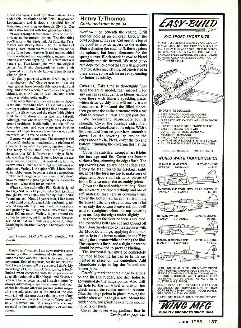
If using flaps, install small spruce or pine blocks alongside a rib to accept screws for flap pushrod attachment. Solder a thin wire loop to each pushrod end where it meets the flap surface and attach with washers and small wood screws. Adjust pushrod length for neutral flap setting; turn clevises to fine-tune.
Use lengths of threaded rod fitted into ends of inner Sullivan rods and adjust so control surfaces are neutral when Goldberg or Du-Bro clevises are attached to servo arms.
Install receiver in foam rubber padding and mount servos as described. Screw metal rods into front ends of rudder and elevator flex-rods and use Goldberg or Du-Bro adjustable fittings on the servo arms.
Wrap the 500 mAh Ni-Cd battery in foam rubber and position it behind the firewall, holding it forward with a rolled foam pad stuffed behind it. Epoxied hooks inside the fuselage on either side of the battery at the bottom corners anchor rubber bands: one set secures the battery, the other holds the windshield/turtledeck unit.
Cowling attachment: rather than screws, use 3/8-in. strips of MonoKote in small pieces to conceal the seam and make the cowl light and easily removable. Position the cowl with bits of masking tape, then iron on the MonoKote strips. The cowl can be peeled off to remove for cleaning or engine work and we have removed it many times successfully.
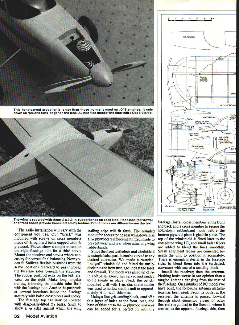
Prop finishing and notes: after carving and sanding a laminated walnut/maple prop, apply a rubbed-on coat of clear dope, rub down with steel wool, and finish with clear polyurethane from a spray can. For final balance, spray more finish onto the lighter blade. A large laminated prop cuts RPM somewhat but produces good thrust and seems to extend engine-run on a given amount of fuel.
Flying
Before flying, ensure the model hangs level when lifted by fingertips under the wing spar location. Add small lead weights to nose or tail if necessary to achieve correct balance (CG near the spar location). Inspect from all angles for warps and misalignment. Use a heat gun and a friend's helping hands to warm and straighten any warps if needed.
Preflight checklist:
- Have an experienced RC flier test-fly if you are a beginner.
- Check flight pack battery charge and that all controls work freely and respond correctly.
- Fill tank with Cox fuel, start engine and bring to peak RPM, then slightly richen needle valve.
Hand-launch technique: hand-launch gently from shoulder height in level attitude directly into the wind while running a few steps. After trimming, you can launch flat-footed. Immediately adjust transmitter trims as needed. Our two models flew with virtually no trimming required.
Flight characteristics: the Henry T flies smoothly, climbs well, and responds well to controls. It loops easily and will spin if stalled with full-left and full-up input; recovery is immediate when controls are neutralized. With proper transmitter trim, the Henry T flies hands-off. Takeoffs and landings are enjoyable — the model tracks straight with little tendency to veer or ground-loop. In buoyant air be prepared for long glides or extended soaring. Do not fly with misaligned or warped surfaces or with the CG rearward of the spar. Use down-flap sparingly.
Some builders have discussed enlarged versions (near 6-ft. span with a .15 or .40 engine). At this writing, a near-6-ft. span version with an altered airfoil, operable flaps, and a .40 four-stroke would be appealing.
My Henry T has provided many hours of relaxed air time at minimal cost. If you decide to build one, good luck and pleasant flying.
Transcribed from original scans by AI. Minor OCR errors may remain.

